


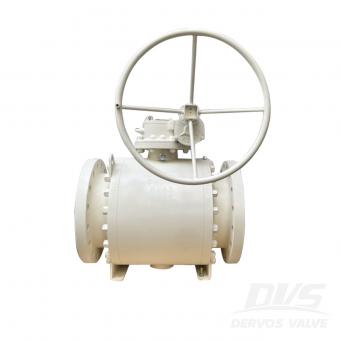
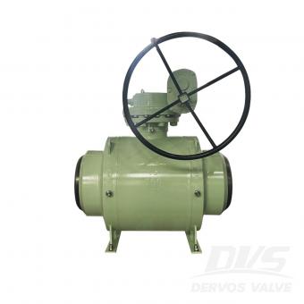
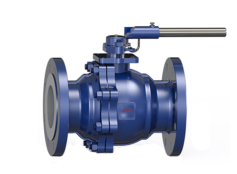
16" x 12" 600LB trunnion mounted ball valve is made according to API6D standard. The valve body is made of A105. It has the structural characteristics of split type, side mounted, fixed ball, reduced diameter. Its connection mode is RF. And it has pneumatic operation mode.

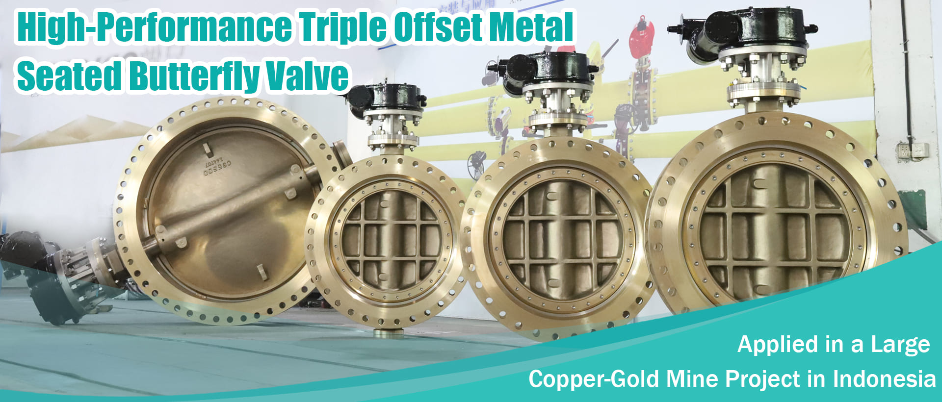
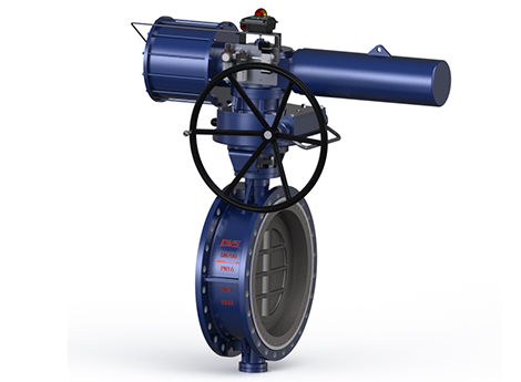
16" 150LB double eccentric butterfly valve twins are made according to API 609 standard. The valve body is made of ASTM A216 WCB. It has the structural characteristics of high performance and dual eccentricity. Two valves share one worm gear head. Its connection mode is wafer. And it has turbine operation mode.

1" 300LB steam trap valve is made according to GB/T22654-2008 standard. The valve body is made of LF2 CL1. It has the structural characteristics of thermodynamic type. Its connection mode is RF.

2" 300LB change over valve is made according to ASME B16.34 standard. The valve body is made of ASTM A216 WCB. It has the structural characteristics of plug cover, the overall internal material is F316L. Its connection mode is RF. And it has Handwheel operation mode.

12" 1500LB cast steel slab gate valve is made according to API 6D standard. The valve body is made of A216 WCB. It has the structural characteristics of body cover bolt, full flow, cleanable pipe, anti-fire design. Its connection mode is RTJ. And it has gearbox operation mode.
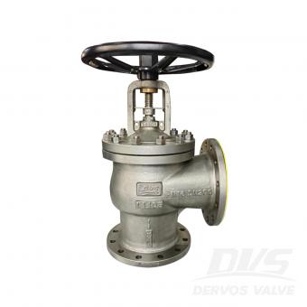
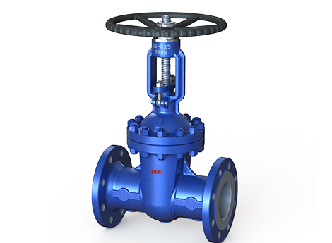
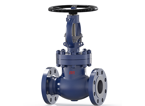
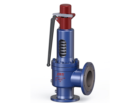
DN200 PN16 angle bellows sealed globe valve is made according to BS EN 13709 standard. The valve body is made of EN 10213 1.4408. It has the structural characteristics of body cover bolt, exposed pole bracket, angle type, bellow seal. Its connection mode is RF. And it has hand wheel operation mode.
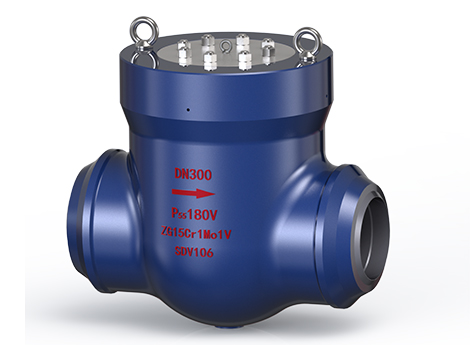
DN300 PN63 ball valve is made according to API 6D standard. The valve body is made of ASTM A105. It has the structural characteristics of fixed ball, full bore, anti-fire, anti-static, and anti-flying valve stem. Its connection mode is EN1092-1 D. And it has worm wheel operation mode.
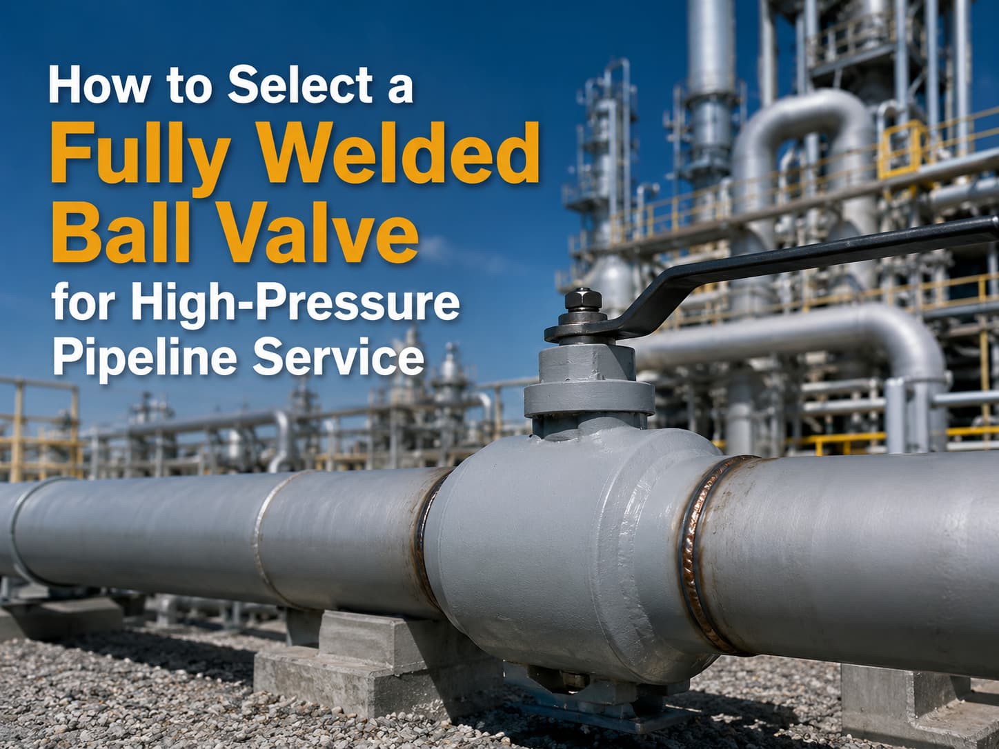
16" 900LB ball valve is made according to API 6D standard. The valve body is made of A350 LF2. It has the structural characteristics of fully welded, fixed ball and full bore. Its connection mode is BW. And it has turbine operation mode.
An API 602 forged gate valve is used for compact, small-bore gate valve service in petroleum, natural gas, chemical, power, and industrial piping. To specify the right design, confirm size, pressure class, material, bonnet type, end connection, port type, trim, seat, testing standard, and service conditions. What Is an API 602 Forged Gate Valve? An API 602 forged gate valve is a compact steel gate valve manufactured to API 602 requirements. API 602 covers gate, globe, and check valves for sizes DN 100 / NPS 4 and smaller in petroleum and natural gas industry applications. Unlike large cast steel gate valves, forged gate valves are usually selected for smaller piping systems where pressure, temperature, vibration, or compact installation matters. Forged construction provides a dense material structure, which is useful for high-pressure and critical service. In simple terms, API 602 is often the better fit when the line is small but the service is demanding. When Should You Use an API 602 Forged Gate Valve? Use an API 602 forged gate valve when the application requires reliable isolation in a compact piping system. It is commonly used in refineries, chemical plants, power plants, oil and gas facilities, steam lines, vents, drains, and utility systems. Typical use cases include: ● Small-bore high-pressure lines ● Steam and condensate service ● Process isolation ● Skid-mounted systems ● Drain and vent connections ● Instrument and auxiliary piping ● Oil, gas, and petrochemical service For larger line sizes or heavy-duty cast steel applications, API 600 may be more appropriate. API 602 and API 600 should not be treated as interchangeable standards. Key Design Choices to Specify Do not specify an API 602 forged gate valve only by size and pressure class. The purchase requirement should define the full valve design. Important items include: Item What to Confirm Size DN / NPS size and bore requirement Pressure class Class 800, 1500, 2500, or project requirement Material A105, F304, F316, F11, F22, LF2, or other grade Bonnet type Bolted bonnet, welded bonnet, or pressure seal End connection Socket weld, threaded, butt weld, or flanged Port Full port or regular port Trim Stem, wedge, seat, and hardfacing material Operation Handwheel, gearbox, or actuator if required Testing API 598 or project-specified testing These details affect sealing, pressure capability, maintainability, and installation. Bonnet and End Connection Selection Bonnet type should match pressure, temperature, and maintenance needs. Bolted bonnet designs are common and easier to service. Welded bonnet designs reduce potential leakage paths but are less convenient to disassemble. Pressure seal bonnets may be considered for higher-pressure service, depending on the design and project requirement. End connection is equally important. Socket weld ends are common for small-bore forged valves. Threaded ends may be...
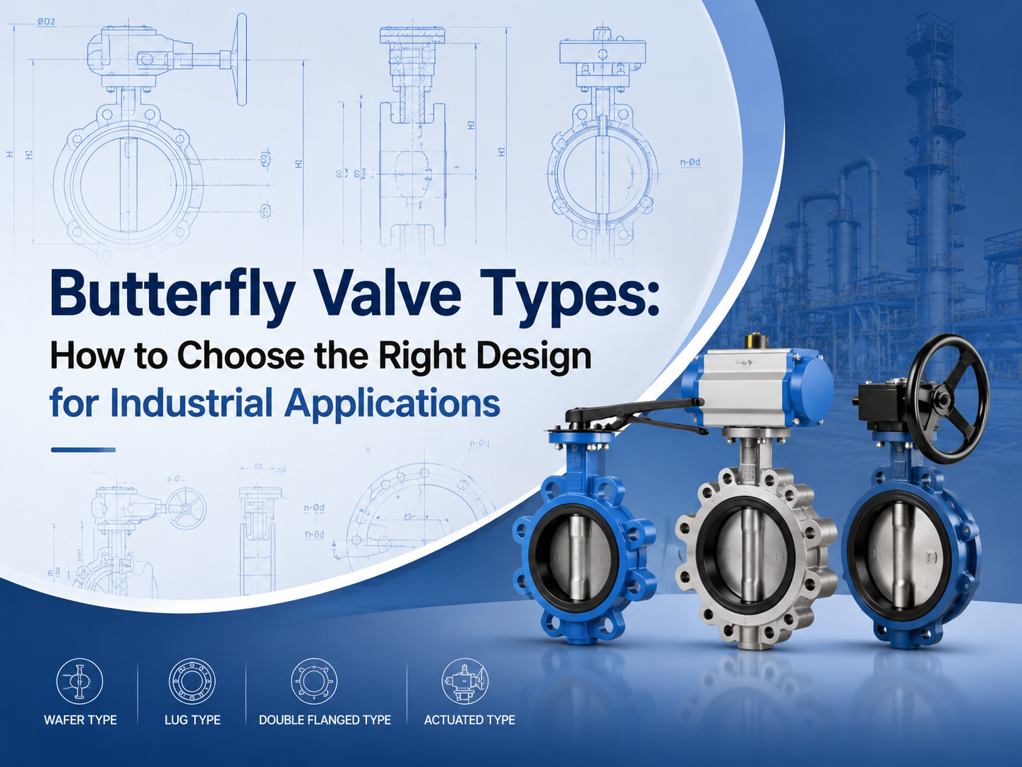
The main butterfly valve types include concentric, double offset, triple offset, wafer, lug, flanged, soft-seated, metal-seated, manual, pneumatic, and electric butterfly valves. The right choice depends on pressure, temperature, media, leakage requirement, installation space, and operation frequency. What Are the Main Butterfly Valve Types? Butterfly valves are usually classified by disc design, body connection, seat material, and actuation method. This classification is important because two valves may both be called butterfly valves, but their service limits can be very different. A butterfly valve uses a rotating disc to isolate or regulate flow. Because of its compact structure, light weight, and quarter-turn operation, it is widely used in water treatment, power plants, chemical processing, HVAC, marine systems, and general industrial pipelines. For buyers, the key question is not simply “which type is cheaper?” It is “which type can handle the actual pressure, temperature, media, and sealing requirement?” Concentric Butterfly Valve A concentric butterfly valve has the stem located on the centerline of the valve body and disc. It is also called a centerline butterfly valve. This type is commonly used for low-pressure and general-service applications, especially with water, air, and non-aggressive fluids. It is simple, economical, and easy to maintain. The limitation is seat wear. During opening and closing, the disc stays in contact with the soft seat for much of its movement. For higher pressure, higher temperature, or stricter shutoff requirements, double offset or triple offset designs are often more suitable. Double Offset Butterfly Valve A double offset butterfly valve uses two offsets to reduce friction between the disc and seat. This improves sealing performance and helps extend service life compared with a basic concentric design. Double offset butterfly valves are often selected for medium-pressure industrial service, including oil and gas, water supply, power generation, and chemical systems. They are useful when the application needs better durability but does not require a full metal-seated triple offset design. This type is also commonly called a high-performance butterfly valve. Before selection, buyers should confirm the pressure class, seat material, shaft sealing design, and expected operation frequency. Triple Offset Butterfly Valve A triple offset butterfly valve adds a third geometric offset to create a more advanced sealing structure. It is typically used for high-temperature, high-pressure, or severe-service applications. The design reduces rubbing between the sealing surfaces during operation. Many triple offset butterfly valves use metal seats, making them suitable for steam, oil and gas, chemical, and other demanding media. For these applications, standards and testing matter. Buyers often need t...
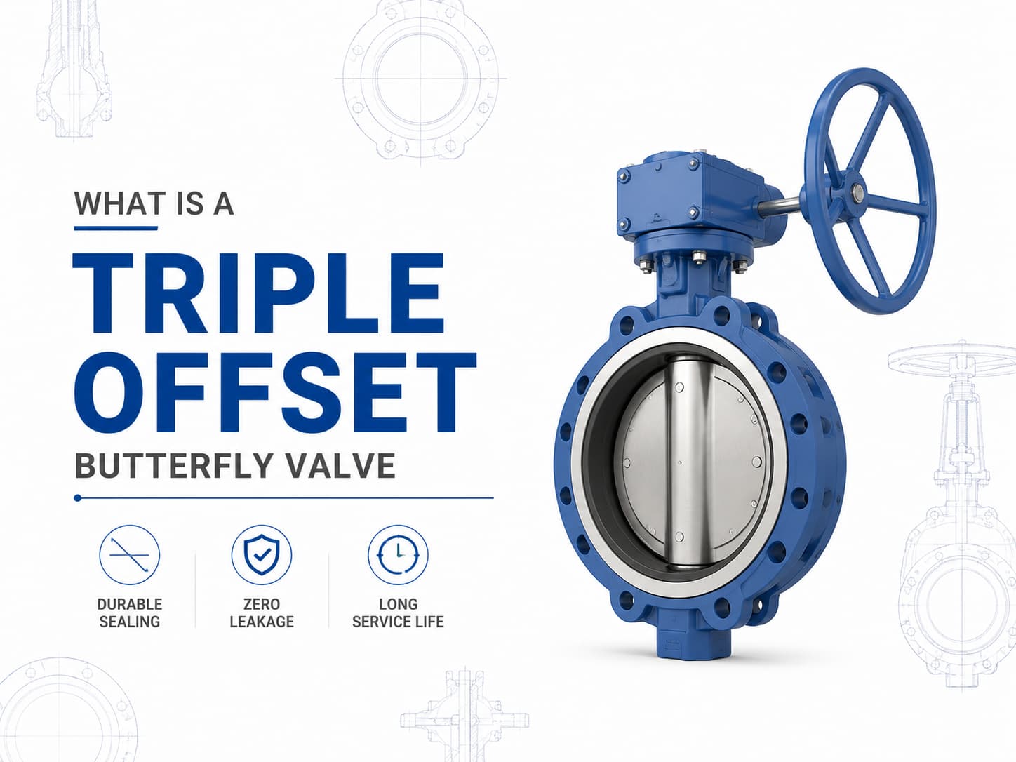
A triple offset butterfly valve is a high-performance isolation valve designed for applications where conventional resilient-seated or double offset butterfly valves cannot meet pressure, temperature, or leakage requirements. By using a three-offset sealing design, the valve achieves a metal-to-metal sealing mechanism with reduced friction between the disc and seat during operation, making it suitable for demanding services such as oil and gas, petrochemical, power generation, LNG, steam, and industrial process systems. Triple Offset Butterfly Valve Design and Working Principle Unlike a concentric butterfly valve, where the shaft is positioned at the centerline of the disc and seat, a triple offset butterfly valve incorporates three independent geometric offsets. The first offset moves the shaft away from the centerline of the valve body, the second offset shifts the shaft from the pipeline centerline, and the third offset introduces a conical sealing surface instead of a circular sealing profile. This geometry allows the disc to move away from the seat immediately after rotation begins, eliminating rubbing between sealing surfaces. The main advantage of this design is that the sealing force is generated by torque rather than continuous compression of soft materials. If the application requires high-temperature service, then a metal-seated triple offset butterfly valve is often preferred because elastomer seats may degrade under elevated temperatures. If the medium contains abrasive particles or aggressive chemicals, then material selection for the disc, seat, and body becomes critical to prevent erosion, corrosion, and leakage during long-term operation. Triple Offset Butterfly Valve Standards and Materials A triple offset butterfly valve is commonly manufactured according to standards such as API 609, EN 593, and ISO 5752, with pressure ratings ranging from Class 150 to Class 600 and higher depending on design requirements. Typical materials include carbon steel, stainless steel, duplex stainless steel, aluminum bronze, and nickel-based alloys. For corrosive seawater applications, aluminum bronze alloys such as C95500 or C95800 may be selected, while sour service applications may require materials compliant with NACE MR0175/ISO 15156 requirements. Triple Offset Butterfly Valve Sealing Performance and Leakage Control The sealing performance of a triple offset butterfly valve depends on the interaction between the sealing ring, seat surface finish, operating torque, and material compatibility. Since the sealing surfaces contact only at the final closing position, mechanical wear is significantly reduced compared with traditional butterfly valve designs. If zero leakage is required for critical isolation, then the valve design, pressure class, and applicable leakage standard, such as API 598 or ISO 5208, must be considered during specification. Triple Offset Butterfly Valve Applications and S...
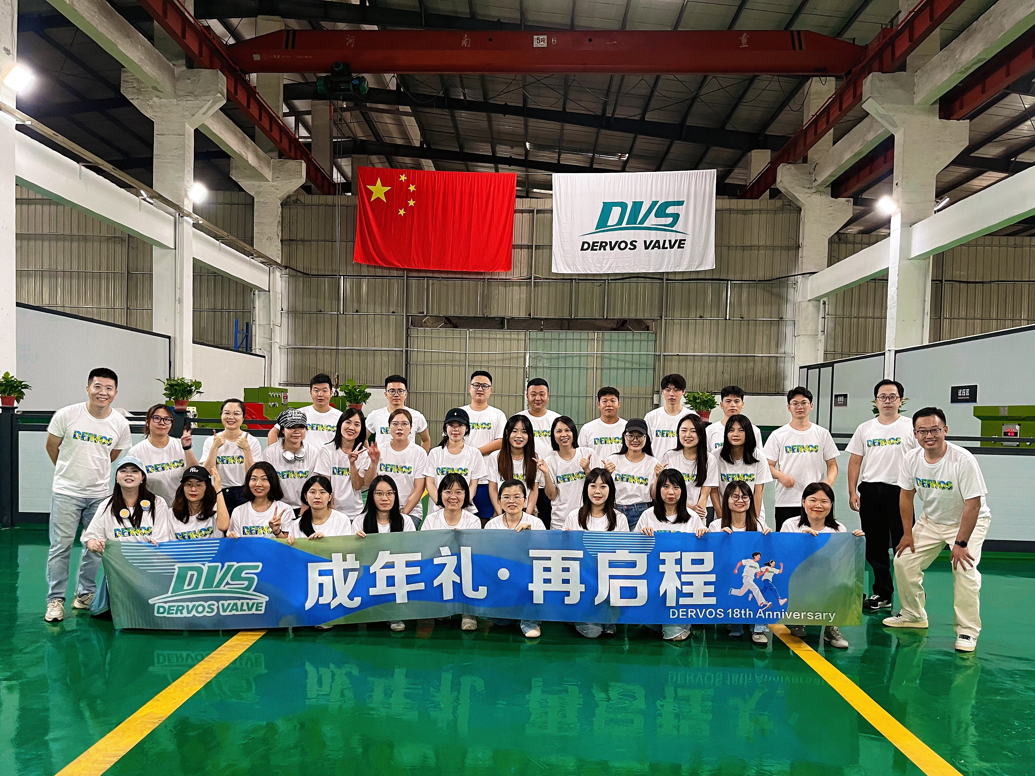
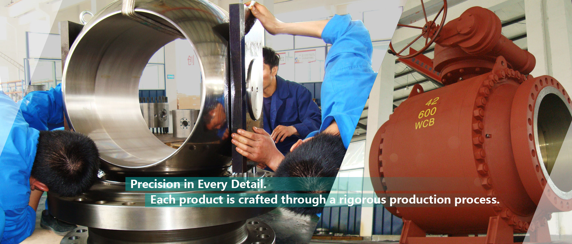
In 2026, DERVOS VALVE proudly celebrates its 18th anniversary, marking an important milestone in the company's journey. To commemorate this occasion, DERVOS VALVE organized a three-day anniversary celebration, bringing together all employees to reflect on the company's achievements over the past eighteen years, look ahead to future development, and further strengthen team cohesion through meaningful activities and shared experiences. Reflecting on 18 Years of Growth From raw material management and precision machining to assembly and product testing, every stage of production reflects DERVOS VALVE's unwavering commitment to quality. Over the past eighteen years, DERVOS VALVE has continuously improved its manufacturing system while enhancing product quality and customer service capabilities. Today, our industrial valves are widely used across the oil and gas, chemical, power generation, water treatment, LNG, and other industrial sectors, providing reliable valve solutions to customers worldwide. Building Consensus for Future Development During the anniversary celebration, DERVOS VALVE also held its mid-year communication meeting. The meeting reviewed the company's performance over the first half of the year and outlined key objectives for future development. Representatives from different departments exchanged insights on production management, quality improvement, and cross-functional collaboration, sharing practical experience, reviewing achievements, and discussing future goals together. The meeting further strengthened communication among departments, reinforced team alignment, and injected new momentum into the company's long-term development. Embracing Nature Together In addition to the company's anniversary activities, DERVOS VALVE organized a group excursion to experience the beauty of nature. Surrounded by picturesque landscapes, employees enjoyed the scenic environment and explored the local culture in a relaxed and enjoyable atmosphere. The trip provided an opportunity to unwind while fostering stronger relationships among colleagues. This memorable experience enriched the anniversary celebration, strengthened team spirit, and inspired everyone with renewed energy for the work ahead. Eighteen Years of Commitment, Looking Ahead Eighteen years represent not only growth and achievement, but also the beginning of a new chapter. Since its establishment, DERVOS VALVE has remained dedicated to the design, manufacturing, and global supply of industrial valves. Through continuous improvements in product development, manufacturing capabilities, and quality management, the company has provided reliable valve products and technical support to customers across a wide range of industries worldwide. Looking ahead, DERVOS VALVE will continue to focus on product innovation, manufacturing excellence, and long-term...
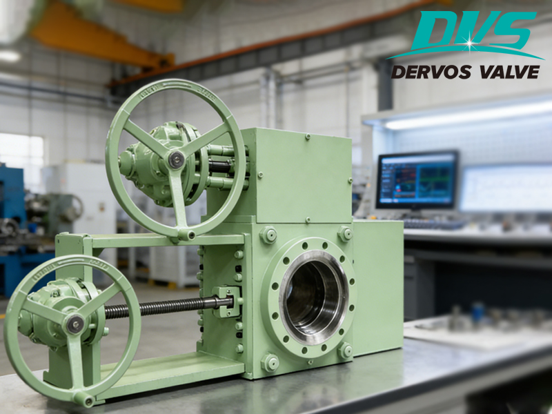
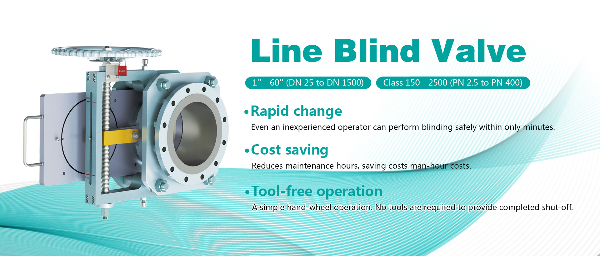
A major South African oil client deployed the DVS sliding blind valve in a multi-media pipeline system requiring frequent switching between oil products, natural gas, and chemical solvents. Since installation, the system has achieved stable zero-leakage operation. The valve’s online operation under pressure has completely eliminated the need for shutdown and depressurization, while significantly improving onsite maintenance safety. Customer Challenge: Seal Failure and Lack of Positive Isolation During Frequent Multi-Media Switching The client is a large oil processing and storage company in South Africa. Their pipeline network frequently switches between multiple media, including oil products, natural gas, and chemical solvents. Due to the significant differences in media characteristics, the system places extremely high demands on valve sealing performance, corrosion resistance, and operational safety. While using conventional gate valves and ball valves, the client faced the following critical operational issues over the long term: Issue Type Conventional Gate / Ball Valve Performance Actual Operational Impact Seal failure and internal leakage Seals degrade over time and cannot guarantee zero leakage Media leakage creates serious safety and environmental risks Shutdown and depressurization required for maintenance Pipelines must be fully depressurized before maintenance Long downtime and significant production losses Inability to achieve true positive isolation Isolation depends on sealing components with limited reliability Risk of cross-contamination during media switching The client specifically requested a valve solution that could: ● Operate without relying on seals ● Support operation under pressure ● Provide absolute physical isolation DVS Sliding Blind Valve Solution: Physical Isolation + Online Operation + Zero Leakage The DVS sliding blind valve uses a solid blind plate to physically block the media passage. This design fundamentally eliminates the risks associated with conventional seal-dependent valves. The following four technical advantages played a key role in solving the client’s operationalchallenges: Absolute Physical Isolation with Zero Leakage The solid blind plate directly blocks media flow, eliminating seal aging and seal failure issues. This ensures true zero-leakage performance under all operating conditions. Online Operation Under Pressure Without Shutdown The valve can switch between open and closed positions while the system remains pressurized. No depressurization or production shutdown is required, dramatically reducing downtime and operational safety risks. External Position Indicator Prevents Misoperation An external position indicator clearly displays whether the valve is open or closed. Operators can instantly verify valve status, significantly reducing the risk of operational mistak...
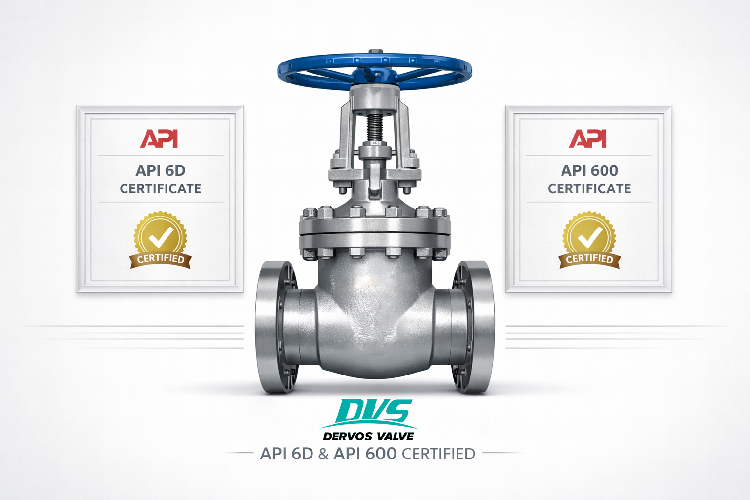
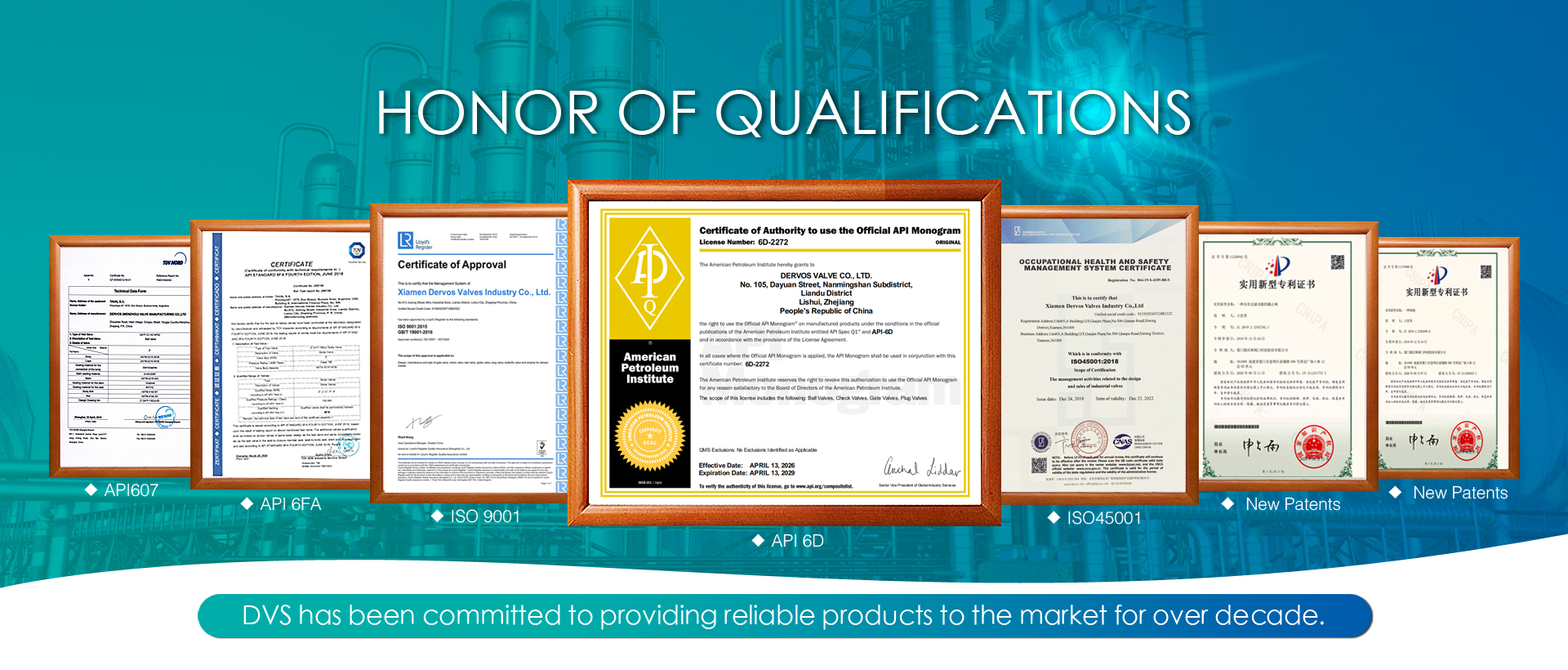
Recently, DERVOS Valve successfully passed the audit by the American Petroleum Institute (API). The company’s API Spec 6D certification for pipeline valves has been renewed, and the API 600 certification has also been issued. Both certificates are valid through 2029. What is an API6D certificate? API 6D is an internationally recognized standard for valves used in oil and gas pipeline transportation systems. It covers the full process requirements for design, manufacturing, and inspection of products such as ball valves, gate valves, and check valves. The certification typically requires renewal audits every three years. What is an API600 certificate? API 600 is an internationally recognized standard for steel gate valves used in oil and gas refinery applications. It defines requirements for design, materials, manufacturing, inspection, and testing. This certification is generally subject to renewal every three years to maintain validity. According to available information, the audit covered multiple aspects, including quality management system operation, production process control, inspection equipment calibration, and personnel qualifications. During the audit, the API inspection team conducted an on-site review of the entire process at DERVOS Valve, from raw material procurement to final product delivery. A representative from the company’s quality department stated that DERVOS Valve has been continuously improving its standardized system management and has established a quality control system covering the full product lifecycle. Key production processes are supported by standardized work instructions, and inspection records are fully traceable to individual orders. The successful renewal of these certifications demonstrates that DERVOS Valve continues to meet API requirements in product manufacturing and quality assurance within the industrial valve sector. It also supports the company’s qualification to supply products for international projects such as oil and gas pipelines and LNG receiving terminals. The company stated that it will continue to focus on standardized production and process management to ensure the effective operation of its quality management system.
If you are interested in our products and want to know more details,please leave a message here,we will reply you as soon as we can.
Copyright © 2015-2026 DERVOS VALVE CO.,LTD.All Rights Reserved Blog / Sitemap / XML / Privacy Policy


"Everything is perfectly made. We are grateful for the confidence you are showing in our organization and fully trust our hard-work will be fruitful for both of our companies. You are truly a GEM for Dervos Valves. Our best compliments to you!"
"Your customer service is outstanding. ... ... The check valves works fine and the customer service certainly makes up for it. ... ... The customer service couldn’t be better."
"We are very satisfied with all your kind business supports. You are always kindly answering all our questions. So, we thank you for all your efforts. When we have any new project, we will readily make a contact with you!"
"I’ve received your document today. Thank you so much. Our engineer says your report seems to have been done quite well, he appreciated, of course we haven’t got the vannes so we haven’t had a check, but I believe there won’t be problem, hope so."
"Thank you for engaging with our organisation regarding Dervos. We place various orders with Dervos and products were always completed ex-factory, to drawing and within the time periods indicated. Dervos is a very proud company and place huge emphasis in delivering quality products to their customers."