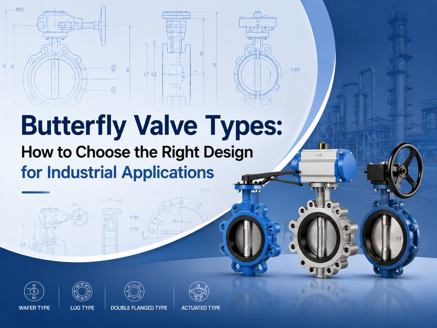
Butterfly Valve Types: How to Choose the Right Design for Industrial Applications
Jul 24, 2026
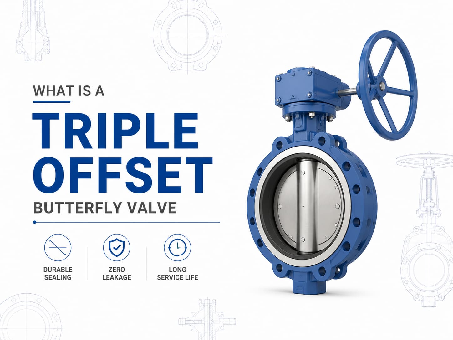
The main butterfly valve types include concentric, double offset, triple offset, wafer, lug, flanged, soft-seated, metal-seated, manual, pneumatic, and electric butterfly valves. The right choice depends on pressure, temperature, media, leakage requirement, installation space, and operation frequency. What Are the Main Butterfly Valve Types? Butterfly valves are usually classified by disc design, body connection, seat material, and actuation method. This classification is important because two valves may both be called butterfly valves, but their service limits can be very different. A butterfly valve uses a rotating disc to isolate or regulate flow. Because of its compact structure, light weight, and quarter-turn operation, it is widely used in water treatment, power plants, chemical processing, HVAC, marine systems, and general industrial pipelines. For buyers, the key question is not simply “which type is cheaper?” It is “which type can handle the actual pressure, temperature, media, and sealing requirement?” Concentric Butterfly Valve A concentric butterfly valve has the stem located on the centerline of the valve body and disc. It is also called a centerline butterfly valve. This type is commonly used for low-pressure and general-service applications, especially with water, air, and non-aggressive fluids. It is simple, economical, and easy to maintain. The limitation is seat wear. During opening and closing, the disc stays in contact with the soft seat for much of its movement. For higher pressure, higher temperature, or stricter shutoff requirements, double offset or triple offset designs are often more suitable. Double Offset Butterfly Valve A double offset butterfly valve uses two offsets to reduce friction between the disc and seat. This improves sealing performance and helps extend service life compared with a basic concentric design. Double offset butterfly valves are often selected for medium-pressure industrial service, including oil and gas, water supply, power generation, and chemical systems. They are useful when the application needs better durability but does not require a full metal-seated triple offset design. This type is also commonly called a high-performance butterfly valve. Before selection, buyers should confirm the pressure class, seat material, shaft sealing design, and expected operation frequency. Triple Offset Butterfly Valve A triple offset butterfly valve adds a third geometric offset to create a more advanced sealing structure. It is typically used for high-temperature, high-pressure, or severe-service applications. The design reduces rubbing between the sealing surfaces during operation. Many triple offset butterfly valves use metal seats, making them suitable for steam, oil and gas, chemical, and other demanding media. For these applications, standards and testing matter. Buyers often need t...
View More