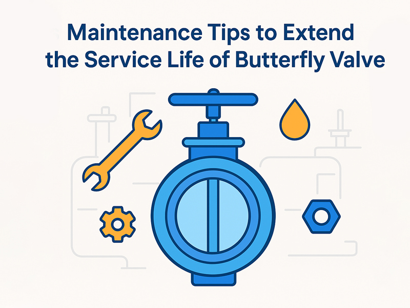
Maintenance Tips to Extend the Service Life of Butterfly Valves
Nov 14, 2025
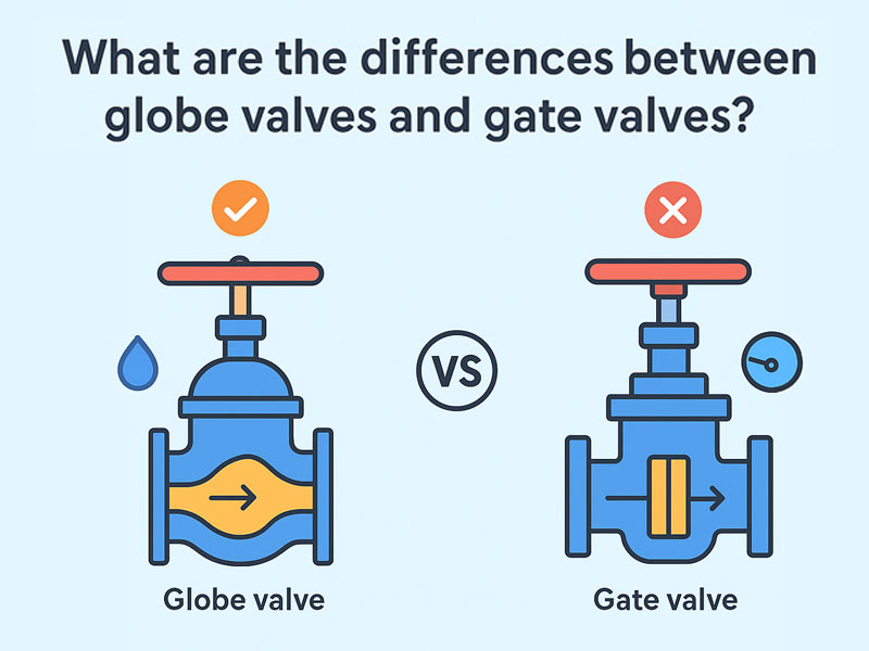
Butterfly valves are widely used as regulating and shut-off devices in industrial piping systems, valued for their simple structure, lightweight design, and rapid open-close operation. They find applications across water treatment, chemical, metallurgical, power, oil, and gas industries. However, even high-quality butterfly valves can experience performance degradation if proper maintenance is neglected over long-term operation.This article explores the structural features, common issues, and maintenance practices to help effectively extend the service life of butterfly valves. 1. Understanding the Operational Characteristics of Butterfly Valves A butterfly valve primarily consists of a valve body, disc, stem, sealing elements, and an actuator. Its operation relies on the rotation of the disc, driven by the stem, to control fluid flow. During operation, the disc remains immersed in the fluid, subject to erosion, corrosion, and pressure shocks. Therefore, the valve’s lifespan is closely related to sealing performance, material selection, and the operating environment. 2. Common Factors Affecting Butterfly Valve Lifespan Frequent Operation and High Differential Pressure High-frequency cycling or prolonged operation under high pressure and flow velocity can cause valve seat wear and stem seal aging. Corrosive Media and Sediment Build-Up Chemical fluids or particulate-laden media can corrode the disc and clog sealing surfaces, reducing smooth operation. Improper Installation Misalignment between the valve and pipeline, or uneven bolt tightening, may lead to eccentric disc friction and damage to sealing elements. Lack of Regular Maintenance Neglecting routine cleaning and lubrication can increase operating torque, accelerate seal wear, and shorten the valve’s overall service life. 3. Maintenance Tips to Extend Butterfly Valve Lifespan 1. Proper Installation as the Foundation Ensure the valve body is aligned with the pipeline center to avoid eccentric stress. Use appropriate gaskets between the valve and flange to prevent localized stress. For actuated butterfly valves, confirm correct travel adjustment to avoid exceeding torque limits. 2. Regular Cleaning and Inspection Periodically remove deposits and debris from the disc surface to prevent seal surface damage. Check stem packing and seals; replace immediately if signs of aging are detected. For pipelines carrying particulate-laden media, flush the valve regularly to prevent clogging. 3. Lubrication and Corrosion Protection Apply grease to the stem, bearings, and drive components regularly to maintain smooth operation. For valves operating in seawater or corrosive environments, select corrosion-resistant coatings or materials such as aluminum bronze or duplex stainless steel. 4. Proper Operation and Control Avoid rapid or forced operation to prevent disc deformation from impact. If the ...
View More