Features of Blind Valve
Apr 10, 2026
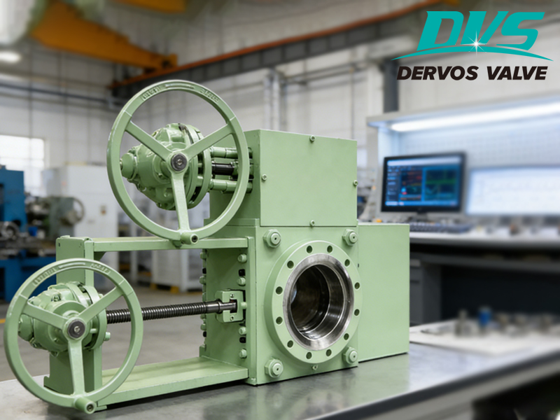
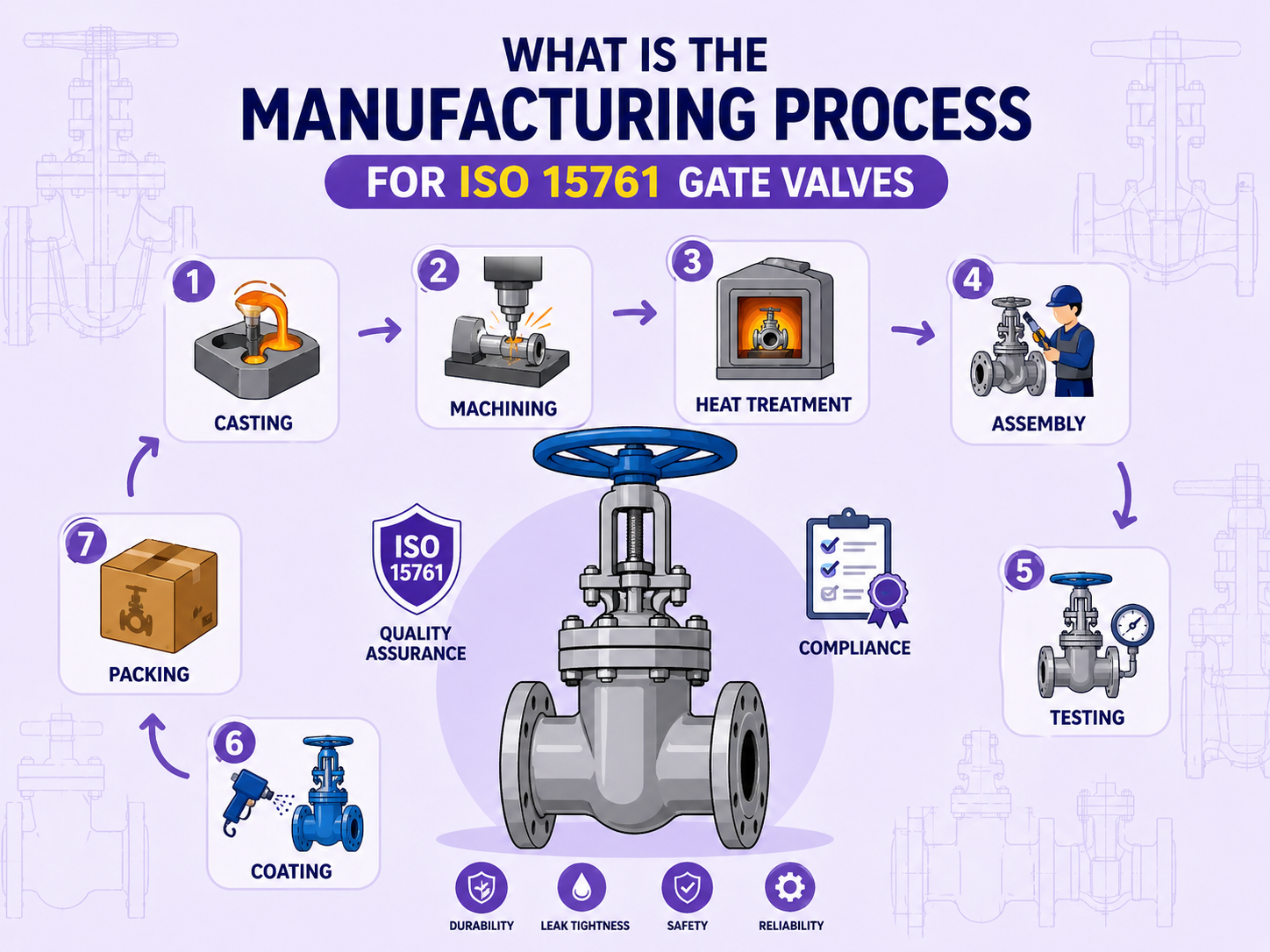
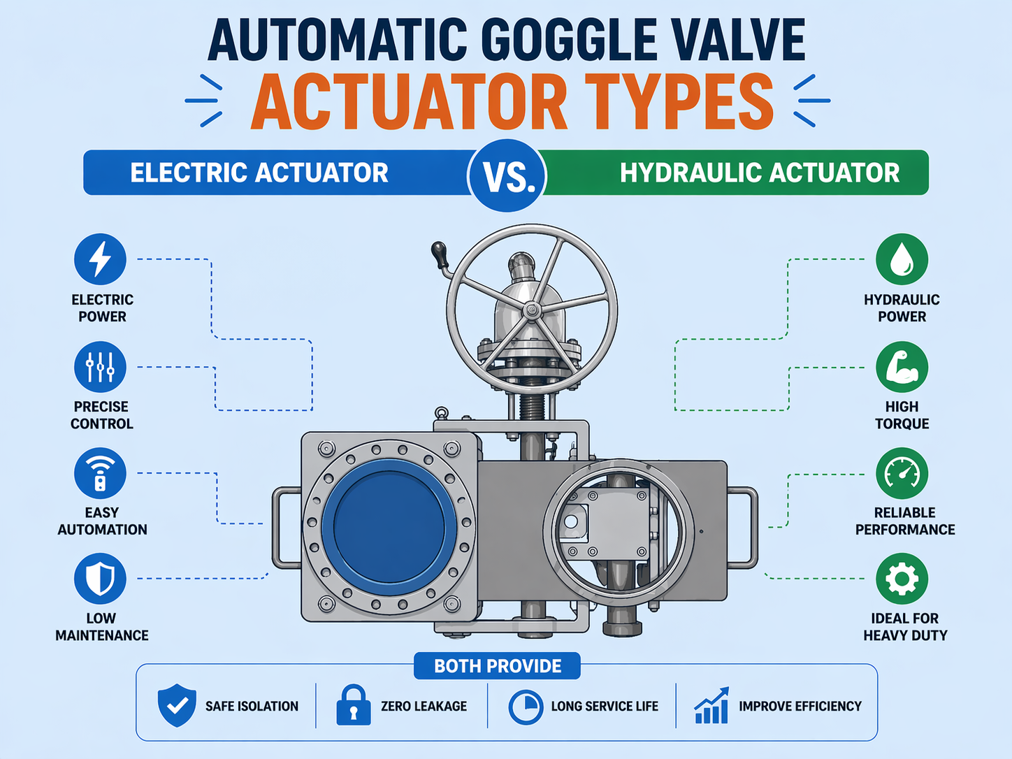
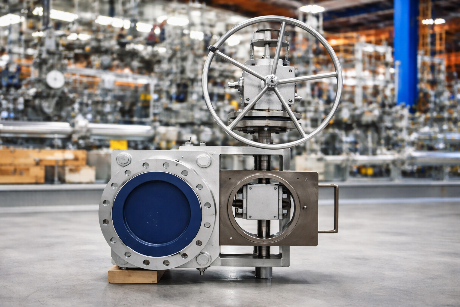
Gate valves and blind valves are both used for pipeline isolation, but they operate on fundamentally different principles.In industrial piping systems, if the objective is true physical isolation (positive isolation), then a blind valve (Blind Valve / Line Blind Valve) is generally more reliable than conventional valves. Instead of relying on seat sealing, it isolates the medium through a solid blind plate, which defines both its application scope and engineering value. The key features of a blind valve can be understood from an engineering perspective as follows: 1. Absolute Physical Isolation If zero leakage is required, then conventional valves (such as gate valves or ball valves) introduce risk, as their performance depends on sealing integrity. Blind valves follow a different logic: ▶ If a solid plate is inserted, then the flow is completely blocked▶ If the blind plate is correctly positioned, then sealing failure is no longer a concern This makes blind valves more suitable for: ● Oil & gas pipeline isolation ● Flammable media (petroleum, LNG, chemicals) ● High temperature steam systems Engineering conclusion:If the project requires verifiable isolation, then a blind valve should be prioritized over sealing-dependent industrial valves. 2. Inline Operation Capability Traditional spade and spacer blinds typically require flange disassembly, which increases operational complexity and introduces safety risks. Blind valves (such as sliding blind valves and swing blind valves) are designed with a different approach: ▶ If frequent switching between operation and maintenance is required, then manual intervention must be minimized▶ If shutdown is not permitted, then switching must be performed under pressurized pipeline conditions (subject to specific design) Therefore: ● Sliding Blind Valve: suitable for limited space and higher automation requirements ● Swing Blind Valve: simple structure, suitable for medium to low switching frequency ● Spectacle Blind Valve: suitable for low-frequency operation and cost-sensitive projects Engineering conclusion:If maintenance is frequent or shutdown is not feasible, then a blind valve with inline operation capability should be prioritized. 3. Mechanical Reliability The reliability of a blind valve does not depend on complex sealing systems, but on: ● Mechanical structural stability ● Material strength (such as A105, WCB, F22, LF2) ● Actuation method (manual, gear-operated, or hydraulic) ▶ If the service conditions involve high temperature, high pressure, or corrosive media, then sealing-based valves are more prone to failure▶ If a blind valve is use...
View More