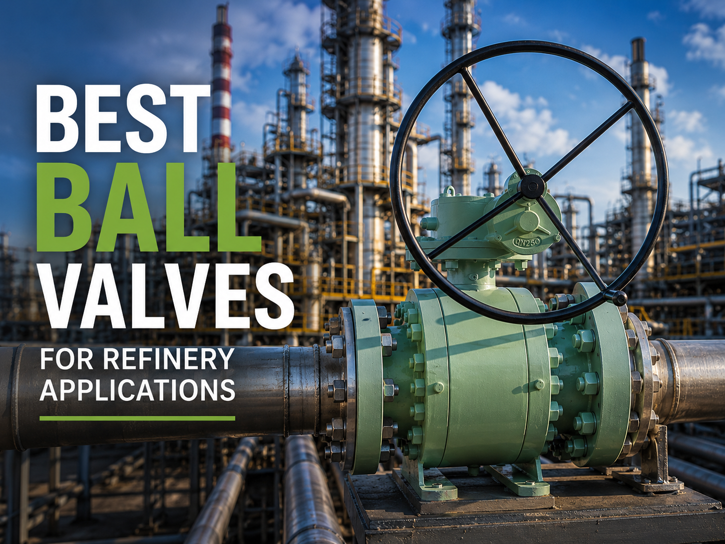
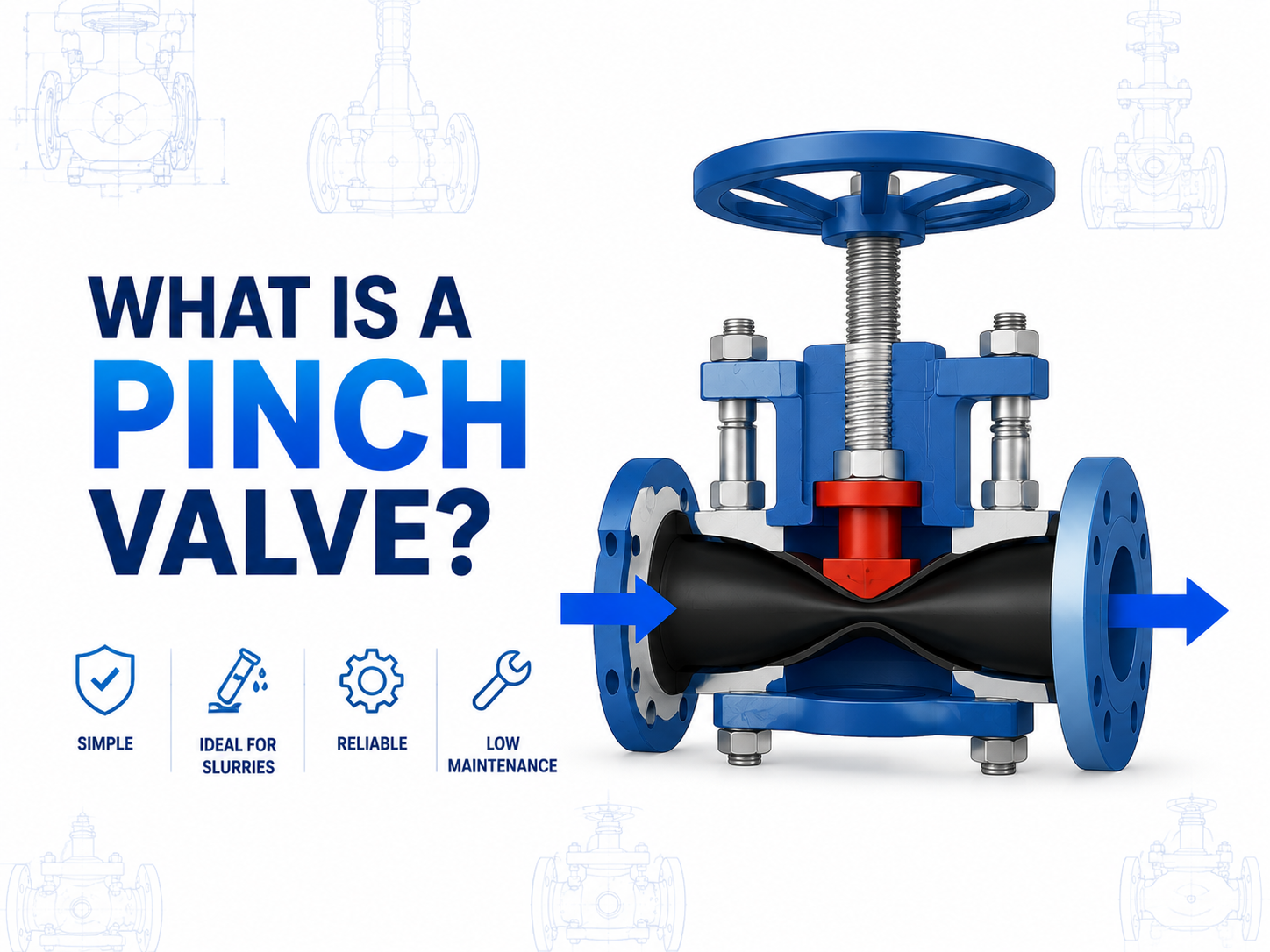
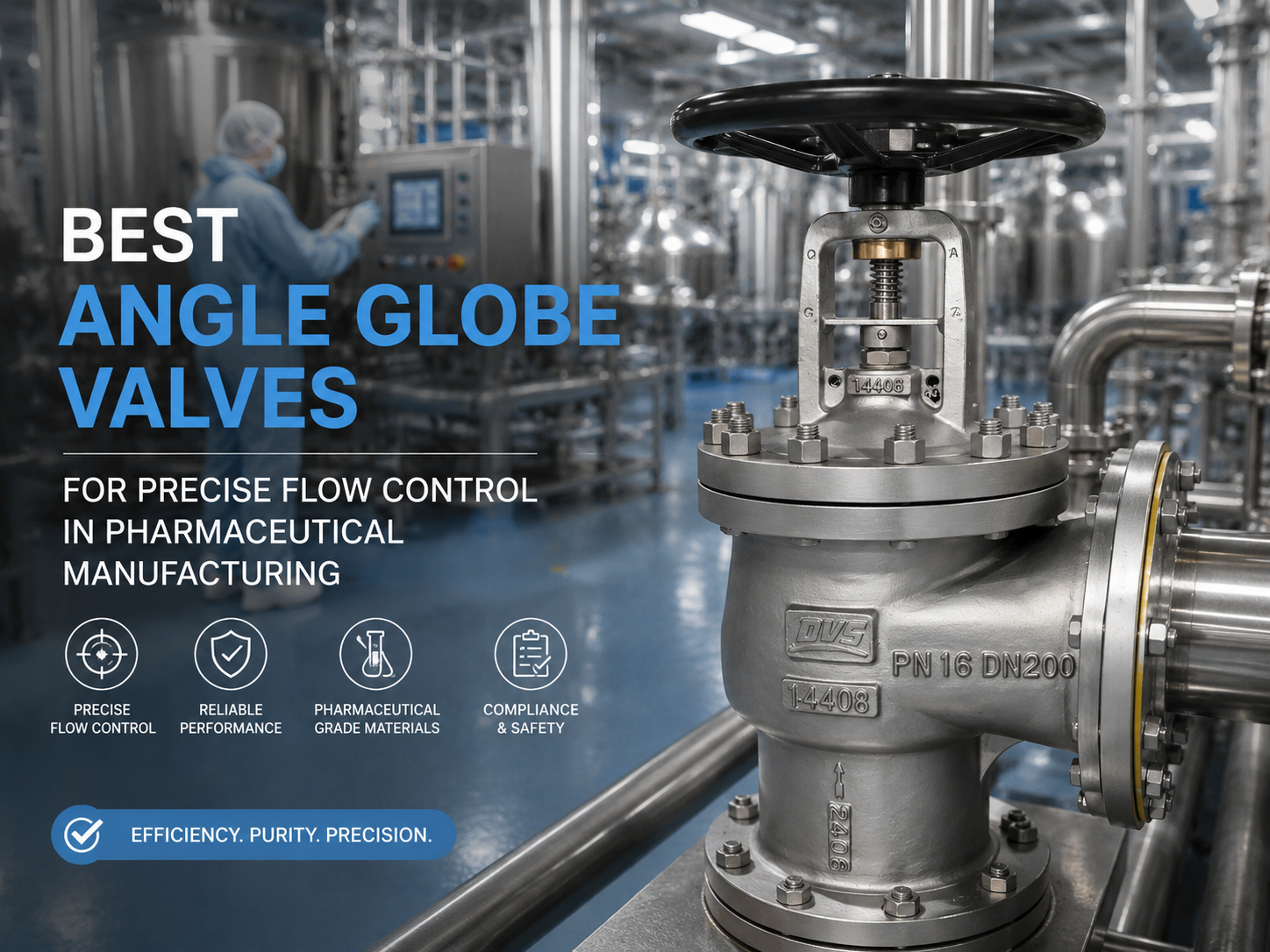
English

English

Get a Quote
Industry Knowledge
  • What Are the Types of Disc Designs in Globe Valves?
    What Are the Types of Disc Designs in Globe Valves? Sep 18, 2025
    Have you ever faced the challenge of selecting the right globe valve disc during pipeline system design or operation? When using a globe valve to control fluid flow, the disc type directly affects sealing performance, flow regulation, and suitability for specific conditions. Understanding the types of discs and their applications can help you make faster, more accurate selections and improve overall system efficiency.   Flat / Standard Disc   Features: The disc has a flat sealing surface, simple structure, and relatively low manufacturing cost. Applications: Commonly used for water, steam, air, and other low-viscosity media. Suitable for medium to low-pressure systems.   Pros & Cons: Provides basic and reliable shutoff, but sealing reliability is moderate. Under long-term high pressure or high temperature, the sealing surface may wear more quickly.   Conical / Tapered Disc   Features: The disc is conical in shape, matching the sealing surface of the valve seat with a smaller contact area. Applications: Ideal for high-pressure conditions or systems requiring precise shutoff, such as steam and oil pipelines. Pros & Cons: Offers excellent sealing performance, but requires greater operating torque for opening and closing.     Plug / Concave Disc   Features: The disc surface is slightly convex, forming point contact with the valve seat, offering high sealing precision. Applications: Suitable for gases, liquids, and some corrosive media, allowing effective flow regulation.   Pros & Cons: Manufacturing cost is higher, but sealing performance and wear resistance are superior to flat discs.   Double Disc   Features: A large disc contains a smaller inner disc. Applications: Commonly used in high-pressure, large-diameter valves. It helps balance pressure and extend valve service life. Pros & Cons: Structurally more complex and more expensive, but ideal for high-pressure, large-diameter applications.     Conclusion     Globe valve discs come in a variety of types, each with unique advantages and suitable working conditions. When selecting a disc, consider the medium type, pressure, temperature, and flow requirements. Choosing the correct disc ensures reliable system sealing, extends valve life, and reduces maintenance costs.
    View More
  • Which Inspection Reports Must Be Requested from the Supplier When Purchasing Gate Valves
    Which Inspection Reports Must Be Requested from the Supplier When Purchasing Gate Valves Sep 12, 2025
    If you have ever experienced project delays due to valve quality issues, or are in the process of selecting qualified valve suppliers for an upcoming industrial project, then understanding the essential inspection reports required when purchasing gate valves becomes critically important. As a key control component in piping systems, the quality of a valve directly affects the safety and reliability of equipment operation. Therefore, when purchasing gate valves, buyers should not only focus on price and delivery time but also ensure that the supplier can provide complete inspection reports.   Mandatory Inspection Reports   ● Material Test Report (MTR) Purpose: To verify that the main components of the valve, such as the body, bonnet, and stem, meet the specified material standards (e.g., ASTM, DIN, EN). Importance: Prevents valve failure under corrosive or high-pressure conditions due to substandard materials.   ● Pressure Test Report Hydrostatic Test: Checks the valve’s strength under the specified pressure. Air Tightness Test: Ensures the valve does not leak at operating pressure. Importance: Confirms that the valve meets the required design pressure rating.   ● Dimension Inspection Report Content: Verifies whether valve structural length, flange dimensions, wall thickness, etc., comply with design and standards (ANSI, EN, GB). Importance: Ensures proper alignment with the piping system and prevents installation deviations.   ● Non-Destructive Test (NDT) Report Methods: Includes Ultrasonic Testing (UT), Radiographic Testing (RT), Magnetic Particle Testing (MT), and Penetrant Testing (PT). Importance: Verifies that castings or welds are free from internal defects, enhancing the valve’s long-term operational reliability.   ● Coating & Painting Test Report Content: Checks paint thickness, adhesion, hardness, salt spray resistance, etc. Importance: Ensures the valve has strong corrosion resistance for outdoor, marine, or chemical environments.   ● Final Inspection Report Content: Includes comprehensive records of appearance, operational performance, markings, packaging, and other inspection items. Importance: Demonstrates that the valve has undergone strict quality control before delivery.   Conclusion   When purchasing gate valves, requiring suppliers to provide complete inspection reports is not only a verification of product quality but also a guarantee of overall project safety and reliability. By reviewing these reports, customers can reduce operational risks, lower maintenance costs, and extend the service life of their equipment.   Q&A   Q1: Why is a Material Test Report (MTR) mandatory when purchasing gate valves? A1: Material determines the valve’s pressure resistance, corrosion resistance, and service life. Different operating conditions require specific materials, so an MTR is necessary to verify compliance.   Q2: Is Non-Destructive Testing (NDT) require...
    View More
  • What is a Stainless Steel Flanged Ball Valve? Complete Technical Overview and Practical Applications Guide for Industrial Use
    What is a Stainless Steel Flanged Ball Valve? Complete Technical Overview and Practical Applications Guide for Industrial Use Aug 28, 2025
    Stainless Steel Flanged Ball Valve is a commonly used industrial valve. Its closure element (the ball) is driven by the valve stem and rotates around the axis of the ball valve, thereby enabling the opening and closing of the pipeline as well as fluid control. In addition to simple on/off functions, stainless steel flanged ball valves can also be used for fluid regulation. In particular, hard-sealed V-port ball valves, relying on the strong shearing force between the V-shaped ball core and the hard alloy-welded seat, are especially suitable for media containing fibers or fine solid particles.   In industrial applications, multi-port stainless steel flanged ball valves can flexibly achieve medium merging, diversion, and flow switching, while also being able to shut off any single passage to ensure normal operation of the remaining pipelines.  these valves generally require horizontal installation to maintain long-term stable performance. According to the driving method, stainless steel flanged ball valves can be classified into manual, pneumatic, and electric types, meeting the needs of different operating conditions.     Standards for Stainless Steel Flanged Ball Valves   To ensure reliable performance and consistent quality, stainless steel flanged ball valves comply with the following standards: • Design and Manufacturing: GB12237-89, API608, API 6D, JPI 7S-48, BS5351, DIN3357; • Flange Dimensions: JB/T74–90, GB9112–9131, ANSI B16.5, JIS B2212–2214, DIN2543,EN1092; • Face-to-Face Dimensions: GB12221-89, ANSI B16.10, JIS B2002, DIN3202,EN558; • Inspection and Testing: JB/T 9092, API 598,API6D. These standards not only guarantee the interchangeability and compatibility of the valves but also ensure their safety and reliability in various industrial environments.     Models and Specifications of Stainless Steel Flanged Ball Valves   Common models and parameters of stainless steel flanged ball valves include: Electric Flanged Ball Valve Q941F: Size DN15–200, Pressure 0.6–10 MPa, Material: Cast Steel / Stainless Steel Carbon Steel ANSI Ball Valve Q41F: Size DN15–200, Pressure 150LB–900LB, Material: Carbon Steel / Cast Steel ANSI Stainless Steel Ball Valve Q41F: Size DN15–200, Pressure 150LB–900LB, Material: Stainless Steel Worm Gear Flanged Ball Valve Q341F: Size DN15–200, Pressure 0.6–6.4 MPa, Material: Carbon Steel / Stainless Steel Pneumatic Stainless Steel Ball Valve Q641F: Size DN15–200, Pressure 0.6–6.4 MPa, Material: Stainless Steel     Main Features of Stainless Steel Flanged Ball Valves   •  Excellent Wear Resistance: The core of the hard-sealed ball valve is overlaid with alloy steel, and the valve seat is surfaced with alloy steel, ensuring strong wear resistance. • Reliable Sealing Performance: Precision grinding guarantees a perfect fit between the ball and the seat, prev...
    View More
  • The Impact of Butterfly Valve Installation Orientation and Spatial Layout on Valve Performance
    The Impact of Butterfly Valve Installation Orientation and Spatial Layout on Valve Performance Aug 01, 2025
    The butterfly valve, as a compact, quick-opening, and low-resistance regulating valve, is widely used in industries such as water supply and drainage, HVAC, power, chemical, and paper-making. However, in practical engineering applications, improper consideration of the butterfly valve’s installation direction and spatial arrangement often leads to valve operating abnormalities, decreased sealing performance, and deviations in control accuracy. In severe cases, it can even cause system failures or frequent maintenance, resulting in unnecessary economic losses. Therefore, a correct understanding of the impact of installation orientation and spatial layout on butterfly valve performance is essential to ensure its reliable operation and extend its service life.     1. The Impact of Installation Orientation on Butterfly Valve Performance   (1) Fluid Flow Direction and Its Effect on Sealing Performance For centerline butterfly valves, where the valve disc rotates around the valve shaft, the force is relatively symmetric, and the fluid flow direction has little impact on the sealing performance. Therefore, the flow direction requirement is not strict during installation. However, for eccentric butterfly valves, especially double-eccentric and triple-eccentric types, the seal design is based on the "flow-assisted compression" principle. That is, when the medium pressure comes from the specified direction, it pushes the valve disc toward the sealing seat, thereby enhancing the sealing effect.   If the valve is installed in the opposite direction of the flow arrow marked by the manufacturer, the reverse fluid flow will wash the valve disc. Not only will the expected sealing effect not form, but it may also create gaps between the sealing surfaces, accelerate valve seat wear, and cause internal leakage, making it impossible to close the valve completely. Therefore, the installation of eccentric butterfly valves must strictly follow the flow direction requirements.   (2) Valve Shaft Orientation and Its Effect on Opening/Closing Torque and Actuator The installation orientation of the valve shaft (horizontal or vertical) has a significant impact on the opening/closing performance, valve body stress, and actuator life. Most medium and small-sized butterfly valves are installed with the valve shaft in the horizontal position. This method facilitates the alignment of the valve body with the pipeline and the arrangement of the actuator.   However, for large-diameter butterfly valves or those installed in high locations or vertical pipelines, the valve shaft is often vertical. In this position, the weight of the valve disc directly acts on the valve shaft, especially when the valve disc is in the open position, where its center of gravity deviates from the axis, creating a large eccentric torque and increasing the axial load during opening and closing. If the actuator does not account for this additional load, it may result in po...
    View More
  • Three Common Causes of Valve Leakage and Emergency Remedies
    Three Common Causes of Valve Leakage and Emergency Remedies May 28, 2025
    In industrial production, valves are critical components for fluid control, and their sealing performance directly impacts system safety and stability. Leakage not only reduces operational efficiency but may also lead to fluid escape, posing serious safety risks. This article outlines three common causes of valve leakage and provides corresponding emergency response recommendations to help you quickly identify issues, take action, and mitigate risks.   1. Seal Surface Wear or Damage   Cause: During long-term operation, sealing pairs (e.g., valve seat and disc, valve ball and seat) suffer from media erosion, particle abrasion, or corrosion, leading to uneven sealing surfaces and resulting in minor or significant leakage. Emergency Measures: · Minor Leakage: Adjust compression force (e.g., tighten bonnet bolts) to temporarily reduce leakage. · Severe Leakage: Immediately shut down the system to replace or regrind sealing components; replace the entire valve if necessary. Prevention Recommendations: Conduct regular inspections, select valves with appropriate materials and wear-resistant designs. For media containing solid particles, use hard-sealing structures.   2. Packing Aging or Gland Loosening   Cause: Valve stem sealing uses packing materials (e.g., graphite, PTFE), which may age, dry, or crack over prolonged use. Temperature fluctuations can also cause gland loosening, leading to leakage at the packing box.  Emergency Measures: · Tighten packing gland bolts to increase packing compression. · If ineffective, add or replace packing material. · Avoid over-tightening to prevent increased operating torque or stem damage. Prevention Recommendations: Regularly replace packing; select materials compatible with the media and operating temperature. For critical equipment, consider spring-loaded packing glands.   3. Casting Defects or Corrosion Perforation in Valve Body/Bonnet   Cause: Some low-quality valves have casting defects such as sand holes or shrinkage cavities. Prolonged exposure to corrosive media can cause localized perforation of the valve body, resulting in uncontrollable leakage. Emergency Measures: · For small leaks, temporary repairs using metal adhesives or cold welding are possible. · Large-scale damage requires immediate valve replacement. · For high-pressure or toxic/hazardous media, no pressurized repair is allowed; follow shutdown procedures strictly.  Prevention Recommendations: Purchase valves from reputable manufacturers; use corrosion-resistant materials (e.g., 304/316L stainless steel). Perform regular wall thickness inspections on critical pipelines.   Common Questions & Answers (Q&A)   Q1: Can all valve leaks be fixed by replacing packing?A: No. Packing replacement is effective only when leakage is due to packing aging or gland loosening. If the leakage stems from seal surface or valve body damage, other me...
    View More
  • Can Oil Pass Through a Strainer? How Pre-Filtration Works in Lubrication Systems
    Can Oil Pass Through a Strainer? How Pre-Filtration Works in Lubrication Systems May 20, 2025
    In any efficient and reliable lubrication system, oil cleanliness is a core factor affecting equipment lifespan and operational efficiency. Strainers, as the front-line filtration devices in lubrication systems, play a critical role in pre-filtration. However, engineers and operators often raise the following questions: Can oil pass through strainers smoothly? What exactly is the function of a strainer? How does it differ from subsequent fine filters?   This article systematically explains the role of strainers in lubrication systems, covering their working principles, pre-filtration objectives, and practical applications across different systems.   1. Can Oil Pass Through a Strainer?   Answer: Yes, but with limitations.   (1) Strainer Structure Allows Oil Flow A strainer is fundamentally a low-precision filter made of stainless steel mesh or perforated metal plates. It features uniform pores, typically sized between 80–500 μm (micrometers), allowing most clean oil to flow through unimpeded.   (2) Contaminants Are Blocked Particles such as metal shavings, seal fragments, and carbon deposits in the oil are intercepted by the strainer, preventing them from entering the oil pump or other critical components.   (3) Oil Temperature and Viscosity Affect Flow Efficiency Low temperatures or high-viscosity oil may reduce flow rates or even cause blockages. This is one reason for low oil pressure during system startup.   2. Objectives and Significance of Pre-Filtration   (1) Protecting the Oil Pump Internal pump components (gears, impellers, or plungers) are highly sensitive to solid particles. Pre-filtration prevents particles from entering the pump, avoiding premature wear or seizure.   (2) Reducing Load on Primary Filters By intercepting large contaminants, strainers allow primary filters (e.g., oil filter cartridges) to focus on finer impurities, extending their service life and maintaining stable system flow.   (3) Lowering System Failure Rates Pre-filtration reduces risks such as pump failure, orifice blockages, and lubrication breakdown caused by foreign particles, enhancing overall system reliability.   3. Typical Applications of Pre-Filtration Devices   Application System Strainer Installation Position Strainer Type Internal Combustion Engine Lubrication Oil sump → Pump inlet Coarse metal strainer Hydraulic Systems Tank outlet → Pump suction port Suction strainer or basket strainer Turbine Lubrication Systems Pump inlet Dual-chamber switchable suction strainer Transmission/Clutch Systems Oil sump → Circulation pump inlet Perforated plate + magnetic strainer   4. Design and Usage Considerations for Strainers   (1) Pore Size Selection Must Align with System Precision Requirements 80–100 μm: Typical for engine oil systems. 150–300 μm: Used in hydraulic equipment. >400 μm:  Suitable for low-pressure or open-loop systems.   (2...
    View More
first page 1 2 3 4 5 6 7 8 9 10 last page
[  A total of  29  pages]

Leave a message

    If you are interested in our products and want to know more details,please leave a message here,we will reply you as soon as we can.

Home

Products

about

contact