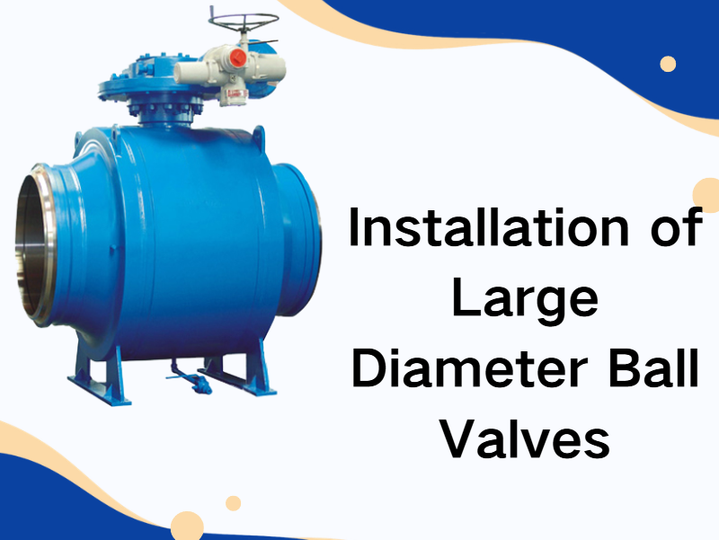
Installation of Large Diameter Ball Valves
Mar 09, 2026
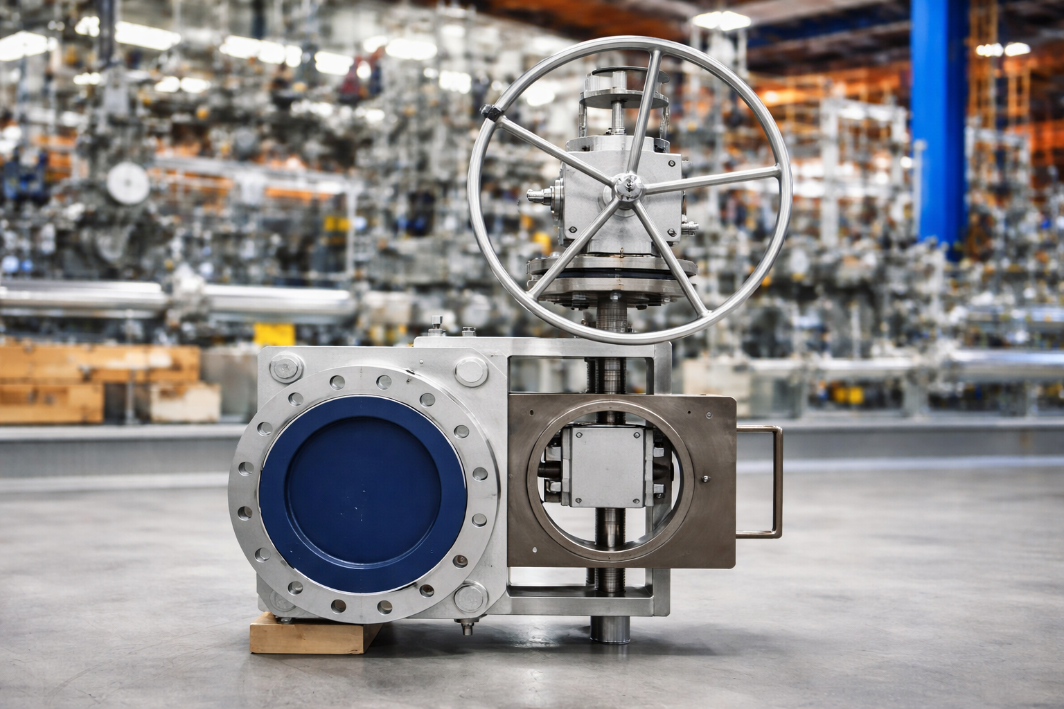
Large diameter ball valves are commonly used in industries such as petroleum and chemical processing, power generation, long-distance pipeline transportation, and large-scale water treatment systems. If installation is not performed correctly, it may lead to sealing leakage, valve jamming, or structural stress damage. Therefore, proper installation practices are essential to ensure long-term stable operation. 1. Pre-installation Inspection If pre-installation inspection is insufficient, operational failures are more likely to occur during service. First, inspect the valve body for transportation damage. If scratches, impact marks, or deformation are found on the valve body or sealing surfaces, installation should be stopped and the supplier should be contacted. Next, verify valve model, pressure rating, and connection standards. If the system design pressure does not match the valve pressure class, operational safety risks may occur. For example, if a low-pressure class valve is mistakenly used in a high-pressure pipeline system, the valve body may experience plastic deformation under water hammer impact. It is also necessary to check the condition of the ball surface and sealing rings. If there are scratches on the ball surface, sealing performance will be reduced. This is especially critical in gas transmission systems where micro-leakage is more likely. 2. Installation Direction Large diameter ball valves usually have a flow direction marking. If the installation direction is incorrect, the following problems may occur: If the fluid flow direction matches the design direction, the operating torque will remain more stable. If the valve is installed in reverse, the stem may experience increased mechanical load, which will accelerate stem wear during long-term operation. For double-seal bidirectional ball valves, although bidirectional flow is allowed, installation according to the marked flow direction is still recommended to ensure more uniform sealing stress distribution. In high-temperature or steam systems, if the installation direction is incorrect, thermal expansion may accelerate sealing ring aging. 3. Pipeline Stress Control Large diameter ball valves are heavy. If installed without proper support, additional bending moments may be transferred to flange connections. If pipeline systems experience axial displacement, pipeline supports should be installed for segmented fixation. If support structures are not provided, the valve body may bear long-term gravitational tensile load, eventually causing flange seal failure. It is generally recommended to install independent supports on both sides of large diameter ball valves. If the pipeline system is subject to thermal expansion and contraction, expansion compensation devices must be installed; otherwise, sealing surfaces may gradually fail. 4. Bolt Tightening Process Flange connections of large diameter ball valves usually ...
View More