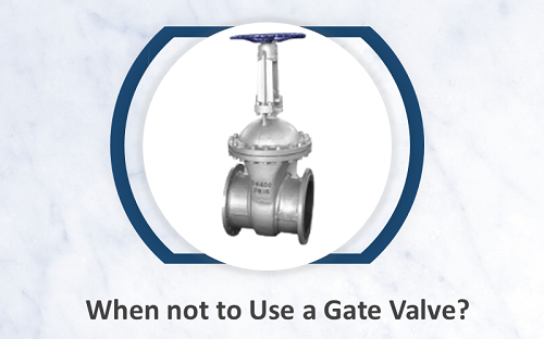
English

English

Get a Quote
Industry Knowledge
  • Precautions for Installing Flanged Check Valves
    Precautions for Installing Flanged Check Valves Jul 26, 2024
    When installing flanged check valves, the following precautions should be taken to ensure their proper operation and long-term use: 1. Preparation before Installation Inspect the valve: Ensure that the valve has not been damaged during transportation and that there are no foreign objects inside the valve body. Clean the pipeline: Clean debris such as weld slag and rust from inside the pipeline to prevent them from entering the valve body. Verify parameters: Check the pressure, temperature, material, and other parameters on the valve's nameplate to ensure they meet the requirements of the working conditions. 2. Installation Position and Direction Flow direction marking: Ensure that the arrow marking on the valve is consistent with the flow direction of the medium in the pipeline. Vertical installation: Check valves are typically installed vertically, with the valve disc free to open and close. When installed horizontally, ensure that the valve disc can move freely. 3. Flange Connection Align flanges: Ensure that the flanges of the pipeline and valve are aligned to avoid offset or stress concentration. Flange gasket: Select the appropriate gasket material and place it correctly between the flanges to prevent leakage. Bolt tightening: Tighten the flange bolts uniformly in a diagonal sequence, gradually increasing the force to ensure uniform stress on the flange and prevent deformation. 4. Avoid Stress Pipeline support: Install appropriate supports before and after the valve to prevent the weight and stress of the pipeline from concentrating on the valve. Reduce vibration: In pipeline systems with significant vibration, take measures to reduce vibration transmission to the valve and extend its lifespan. 5. Testing and Commissioning Seal test: Conduct hydrostatic or pneumatic testing after installation to check the sealing performance of the flange connections and inside the valve. Function test: Confirm that the check valve can open and close normally during medium flow and stoppage. 6. Regular Maintenance Regular inspection: Regularly inspect the tightness and sealing performance of the flange connections to prevent loosening and leakage. Clean the valve body: Clean the inside of the valve body when necessary to prevent debris accumulation that could affect valve performance. Lubricate components: For check valves requiring lubrication, regularly inspect and add lubricant to ensure flexible valve disc movement. 7. Special Working Condition Considerations High temperature and pressure: In high-temperature and high-pressure conditions, select appropriate gasket and bolt materials to prevent leakage caused by thermal expansion and contraction or stress concentration. Corrosive media: For corrosive media, choose valves made of corrosion-resistant materials and implement corrosion prevention measures. 8. Environmental Requirements Protective measures: When installing in outdoor or corrosive environments, take protective measures for the valve, such as ap...
    View More
  • Structure and Working Principle of Orbit Ball Valve
    Structure and Working Principle of Orbit Ball Valve Jul 25, 2024
    The Orbit Ball Valve, with its unique design and reliable performance, has been widely used in industrial fields such as oil, natural gas, and chemicals. 1. Structure of Orbit Ball Valve The structure design of the Orbit Ball Valve differs from that of a conventional ball valve. Its main components include: (1) Valve body: The body of the Orbit Ball Valve is typically made of forged or cast steel, offering high strength and corrosion resistance, and is capable of withstanding high-pressure and high-temperature environments. (2) Ball: The ball moves within the valve body through a specially designed track and is usually made of stainless steel or nickel-based alloys, providing excellent wear and corrosion resistance. (3) Seat: The seat is the part that comes into contact with the ball, typically made of metal to ensure sealing performance under high pressure and high temperature conditions. (4) Stem: The stem connects the ball to the actuator, responsible for transmitting operational torque to move the ball within the valve body. (5) Sealing System: This includes the seat seal and stem seal, ensuring no leakage of the medium. Seals are typically made of metal or high-performance polymer materials. (6) Actuator: This includes manual operation mechanisms or automated actuators used to control the opening and closing of the valve. 2. Working Principle of Orbit Ball Valve The working principle of an Orbit Ball Valve differs from that of a conventional ball valve, with its core function relying on the track movement and rotation of the ball within the valve body. The opening and closing process of an Orbit Ball Valve is as follows: Closed State: In the closed state, the sealing surface of the ball is tightly pressed against the valve seat, forming a reliable seal and preventing the flow of the medium. Opening Process: (1) Initial Eccentric Movement: When the actuator applies operational torque, the ball first moves eccentrically up or down along the track, gradually disengaging from the valve seat. This process reduces friction between the ball and the seat, preventing wear on the sealing surface. (2) Rotational Movement: After completing the eccentric movement, the ball continues to rotate 90 degrees, fully opening the passage and allowing the medium to flow smoothly through. As the ball's movement and rotation on the track occur in separate steps, the operation is smoother, and the required torque is lower. Closing Process: (1) Initial Rotational Movement: When the actuator operates in reverse, the ball first rotates 90 degrees to the closed position, thereby closing the passage. (2) Eccentric Movement: After the ball completes the rotation, it moves along the track back to the valve seat, forming a seal. This frictionless sealing process ensures high sealing performance and a long service life for the Orbit Ball Valve. 3. Advantages of Orbit Ball Valve (1) Frictionless Sealing: The eccentric and rotational movements of the Orbit Ball Valve are separ...
    View More
  • When is it suitable to choose a Y-type ball valve?
    When is it suitable to choose a Y-type ball valve? Jul 19, 2024
    Y-type ball valves have gained popularity in industrial pipeline systems due to their unique Y-shaped structure and excellent fluid control performance. They are designed to reduce fluid resistance and improve flow efficiency, making them well-suited for specific applications. 1. Situations that require low flow resistance and high flow rates: ①High-flow pipeline systems: The Y-shaped design of the ball valve significantly reduces the resistance as fluid passes through the valve, making it suitable for pipelines that require high-flow control. This design ensures smooth and efficient fluid flow, reducing energy consumption. ②Applications with low pressure drop requirements: In systems sensitive to pressure drop, the low flow resistance characteristics of Y-type ball valves effectively reduce pressure losses in the system, ensuring overall pipeline efficiency. For example, in long-distance transportation pipelines and process flows that require specific pressure maintenance, Y-type ball valves are an ideal choice. 2. Handling high viscosity and media with particles: ①High-viscosity fluids: Y-type ball valves can handle high-viscosity fluids, avoiding excessive flow resistance within the valve. This makes them suitable for the transportation and control of high-viscosity media such as oils, syrups, and slurries. ②Media with particles: Due to their smooth and spacious flow passages, Y-type ball valves effectively prevent particle accumulation and blockages when handling fluids with particles. They are suitable for transporting media such as mud and wastewater. 3. Situations that require frequent operation and adjustment: ①High-frequency opening and closing operations: The design of Y-type ball valves allows them to perform well in frequent opening and closing operations, providing reliable sealing performance and long service life. In situations that require frequent operations, such as flow and direction control, Y-type ball valves are a reliable choice. ②Precise flow control: The flow passage design of Y-type ball valves enables precise flow control, making them suitable for process flows that require fine control of flow rates, such as chemical reactions and pharmaceutical production processes. 4. Installation environments with limited space: Y-type ball valves have a compact structure and occupy minimal space, making them suitable for installation in limited spaces. Whether it is inside equipment, dense pipeline areas, or systems that require high-density installation, Y-type ball valves can adapt flexibly. 5. Systems that require high fluid cleanliness: The design of Y-type ball valves ensures smooth flow passages that are not prone to impurity accumulation, making them easy to clean and maintain. In industries with high requirements for fluid cleanliness, such as pharmaceuticals, food, and beverages, Y-type ball valves are an ideal choice. 6. Cost control and ease of maintenance requirements: Due to their low flow resistance design, Y-type bal...
    View More
  • Difference between Wafer Butterfly Valve and Flanged Butterfly Valve
    Difference between Wafer Butterfly Valve and Flanged Butterfly Valve Jul 19, 2024
    Butterfly valves are essential components in fluid control systems, widely used in various industries for their advantages such as simple structure, compact size, lightweight, flexible operation, and easy installation. They are particularly suited for controlling fluid flow, pressure, and direction. Among the commonly used butterfly valves, there are two main types: wafer butterfly valves and flanged butterfly valves. Different Connection Methods: Wafer Butterfly Valve: The valve body does not have flanges. It is clamped between two pipe flanges using double-ended bolts. Two flange pieces clamp the butterfly valve, which is then fixed with bolts. Flanged Butterfly Valve: The valve body has flanges. The valve is connected to the pipe flanges at both ends using bolts. Different Structures: Wafer Butterfly Valve: The bolts used are relatively long, and it does not have flanges itself. Therefore, it is generally not recommended to install it at the end of the pipeline or in downstream positions that require disassembly. When disassembling the downstream flange, the wafer valve may fall off, causing both ends of the pipeline to be unable to function properly. Flanged Butterfly Valve: Due to the valve body having its own flanges, it is securely connected to the pipe flanges. Even if one end is removed, it will not affect the normal operation of the other end of the pipeline. Different Costs and Construction Requirements: Wafer Butterfly Valve: The longer bolts used and the requirement for high construction accuracy may cause leakage if the flanges are not properly aligned. However, it is convenient to disassemble and has relatively lower cost. However, if there is an issue with one sealing surface, both sealing surfaces may need to be opened for inspection and repair. Flanged Butterfly Valve: Although the cost may be slightly higher, the connection is more secure, and the impact range during maintenance is smaller.
    View More
  • What is a Wafer Ball Valve?
    What is a Wafer Ball Valve? Jul 11, 2024
    The wafer ball valve is a common industrial valve, widely used in various piping systems due to its unique structural design and superior performance. Definition A wafer ball valve is a valve that controls fluid flow by rotating the valve core. Its body is designed in a wafer style, meaning the valve is clamped between two pipeline segments with bolts, eliminating the need for additional space required by traditional flange connections. Wafer ball valves are typically used for applications involving shutoff, distribution, and changing the flow direction. Structural characteristics 1. Compact Design: The wafer ball valve features a wafer-style design, making its structure compact and requiring minimal installation space, ideal for pipeline systems with limited space. 2. Lightweight: Due to the elimination of flanges and bolt connections, the wafer ball valve is relatively lightweight, helping to reduce the load on the pipeline system. 3. Easy Installation and Maintenance: The installation and removal of wafer ball valves are very convenient; simply sandwich the valve between the pipelines and secure it with bolts. This design greatly simplifies the installation and maintenance process of the valve. 4. Good Sealing Performance: Wafer ball valves typically use soft or hard sealing structures, ensuring excellent sealing performance and effectively preventing fluid leakage. Working principle The working principle of the wafer ball valve is relatively simple, primarily involving the rotation of the valve core (ball) to control fluid flow. The specific process is as follows: 1. Opening the valve: When the handle or actuator is rotated, the valve core (ball) rotates 90 degrees, aligning the valve passage with the pipeline passage, allowing fluid to pass through freely. 2. Closing the valve: By rotating the handle or actuator in the opposite direction, the valve core (ball) rotates another 90 degrees, making the valve passage perpendicular to the pipeline passage, blocking the fluid flow and achieving the shut-off function. Advantage 1. Space-saving: The compact design of wafer ball valves takes up less space, making them particularly suitable for installations with limited space. 2. Lightweight: Compared to traditional flanged ball valves, wafer ball valves are lighter, making them easier to transport and install. 3. Easy installation: The installation process of wafer ball valves is simple and quick. They only need to be clamped between the pipes and fixed with bolts, eliminating the cumbersome steps of flange connections. 4. Excellent sealing performance: Wafer ball valves use high-quality sealing materials, providing superior sealing performance suitable for applications requiring high sealing standards. 5. Versatile applications: Wafer ball valves are suitable for various industrial piping systems, such as water treatment, chemical, oil and gas, pharmaceutical, and food industries. Application 1. Water treatment systems: Used to control water flow an...
    View More
  • Introduction to Y-Type Globe Valve
    Introduction to Y-Type Globe Valve Jul 05, 2024
    The Y-type globe valve is a common type of valve widely used in various industrial fields such as petroleum, chemical, power, and water treatment. Its unique design makes it excellent for regulating and shutting off fluid flow, offering high reliability and durability. Structure and Principle The Y-type globe valve consists of main components such as the valve body, bonnet, stem, disc, and handwheel. Its name is derived from the Y-shaped structure of its valve body chamber. This design not only reduces the resistance of fluid passing through but also facilitates the movement of the disc. The stem is driven by a handwheel or an electric actuator. When the stem rises, the disc moves away from the seat, allowing fluid to pass through. When the stem lowers, the disc contacts the seat, cutting off the fluid flow. Features and advantages 1. Low Fluid Resistance: Due to the Y-type structural design, the resistance encountered by the fluid passing through is lower than that of a standard globe valve, resulting in minimal flow loss. 2. Excellent Sealing Performance: The sealing surfaces of the disc and seat are made of hard alloys or other wear-resistant materials, ensuring reliable sealing and long service life. 3. Easy Operation: The handwheel operation is simple, and the valve can be equipped with electric or pneumatic actuators for remote control and automation. 4. Easy Maintenance: The valve body has a simple structure, making it easy to disassemble and maintain, thus reducing maintenance costs. Application area 1. Petroleum and Natural Gas Industry: Used in oil pipelines and natural gas transmission systems, featuring high-pressure resistance and corrosion resistance. 2. Chemical Industry: Suitable for pipeline systems with various corrosive media, possessing excellent anti-corrosion performance. 3. Power Industry: Used in steam and cooling water systems, resistant to high temperature and high pressure. 4. Water Treatment: Utilized in wastewater treatment plants and waterworks for cutting off and regulating water flow. Installation and maintenance 1. Location Selection: Choose the appropriate location based on the pipeline direction to ensure convenient valve operation. 2. Installation Direction: Install according to the medium flow direction markings to avoid improper sealing caused by reverse installation. 3. Regular Inspection: Regularly check the valve's sealing performance and operational flexibility, and replace damaged seals promptly. 4. Lubrication Maintenance: Regularly lubricate the threaded parts of the valve stem to maintain smooth operation.
    View More
first page 1 2 3 4 5 6 7 8 9 10 last page
[  A total of  31  pages]

Leave a message

    If you are interested in our products and want to know more details,please leave a message here,we will reply you as soon as we can.

Home

Products

about

contact