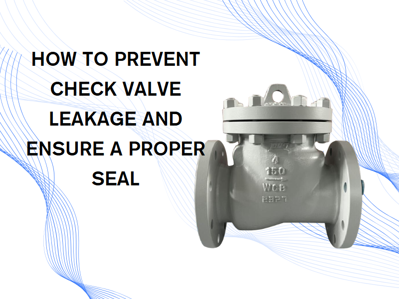
Check Valve Maintenance: When to Replace and How to Fix Common Issues
Nov 06, 2025
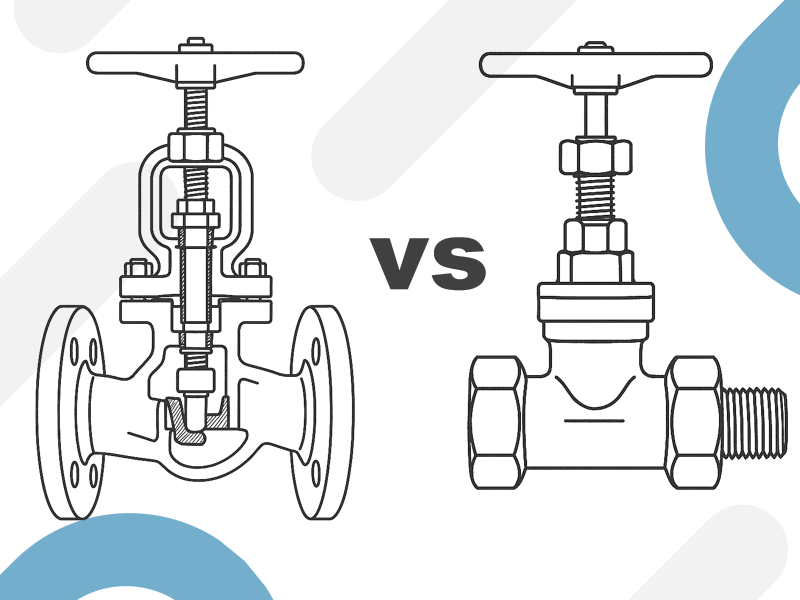
A check valve is a critical device that prevents backflow, widely used in water treatment, oil & gas pipelines, chemical processing, and steam systems. After long-term operation, check valves may experience issues such as leakage, vibration noise, or sticking. If not addressed promptly, these problems can reduce system efficiency and even cause equipment damage or safety hazards. So, how can you tell if a check valve needs replacement? Which faults can be repaired, and which require a full replacement? This article provides a systematic guide. 1. Basic Operating Principle of Check Valves The primary function of a check valve is to automatically prevent backflow. When fluid flows in the intended direction, the valve disc is pushed open by pressure; when flow reverses, the disc closes automatically, using either its own weight or a spring, preventing backflow. Common types include: Lift Check Valve Swing Check Valve Dual Plate Wafer Check Valve Ball Check Valve Although their designs vary, the key criteria for determining whether a check valve needs replacement remain the same: sealing performance, operational smoothness, and structural integrity. 2. How to Determine if a Check Valve Needs Replacement Visible Leakage (Internal or External) If fluid continues to flow backward when the valve is closed, it indicates significant wear or deformation of the sealing surfaces, preventing an effective seal. If the leakage exceeds system tolerances and cannot be corrected by cleaning or resurfacing, the valve or its sealing components should be replaced. Sticking or Inflexible Valve Disc After long-term operation, the valve stem, guides, or disc may become stuck due to scaling, corrosion, or debris. If cleaning, descaling, or lubrication fails to restore smooth operation, replacement is recommended. Excessive Noise or Vibration Frequent opening and closing or rapid disc rebound can cause vibration or knocking sounds. This is usually due to spring failure, loose valve components, or worn guides. Persistent or frequent noise should trigger inspection of the valve’s structural integrity and consideration for replacement. Corroded or Cracked Valve Body or Cover Exposure to acidic, alkaline, or high-temperature fluids can corrode or crack the valve body, compromising structural strength and posing safety risks. Such damage cannot be repaired and requires full valve replacement. Frequent Backflow or Abnormal System Pressure Fluctuations Poor sealing or delayed valve response can cause system pressure variations, including water hammer. If repeated adjustments do not resolve the issue, it indicates aging of the internal spring or disc mechanism, necessitating timely replacement. 3. Common Fault Diagnosis and Solutions Fault: Valve fails to close completely, causing backflow Cause: Worn sealing surfaces, deformed disc, or trapped debris Solution: Remove ...
View More