An API 602 forged gate valve is used for compact, small-bore gate valve service in petroleum, natural gas, chemical, power, and industrial piping. To specify the right design, confirm size, pressure class, material, bonnet type, end connection, port type, trim, seat, testing standard, and service conditions. What Is an API 602 Forged Gate Valve? An API 602 forged gate valve is a compact steel gate valve manufactured to API 602 requirements. API 602 covers gate, globe, and check valves for sizes DN 100 / NPS 4 and smaller in petroleum and natural gas industry applications. Unlike large cast steel gate valves, forged gate valves are usually selected for smaller piping systems where pressure, temperature, vibration, or compact installation matters. Forged construction provides a dense material structure, which is useful for high-pressure and critical service. In simple terms, API 602 is often the better fit when the line is small but the service is demanding. When Should You Use an API 602 Forged Gate Valve? Use an API 602 forged gate valve when the application requires reliable isolation in a compact piping system. It is commonly used in refineries, chemical plants, power plants, oil and gas facilities, steam lines, vents, drains, and utility systems. Typical use cases include: ● Small-bore high-pressure lines ● Steam and condensate service ● Process isolation ● Skid-mounted systems ● Drain and vent connections ● Instrument and auxiliary piping ● Oil, gas, and petrochemical service For larger line sizes or heavy-duty cast steel applications, API 600 may be more appropriate. API 602 and API 600 should not be treated as interchangeable standards. Key Design Choices to Specify Do not specify an API 602 forged gate valve only by size and pressure class. The purchase requirement should define the full valve design. Important items include: Item What to Confirm Size DN / NPS size and bore requirement Pressure class Class 800, 1500, 2500, or project requirement Material A105, F304, F316, F11, F22, LF2, or other grade Bonnet type Bolted bonnet, welded bonnet, or pressure seal End connection Socket weld, threaded, butt weld, or flanged Port Full port or regular port Trim Stem, wedge, seat, and hardfacing material Operation Handwheel, gearbox, or actuator if required Testing API 598 or project-specified testing These details affect sealing, pressure capability, maintainability, and installation. Bonnet and End Connection Selection Bonnet type should match pressure, temperature, and maintenance needs. Bolted bonnet designs are common and easier to service. Welded bonnet designs reduce potential leakage paths but are less convenient to disassemble. Pressure seal bonnets may be considered for higher-pressure service, depending on the design and project requirement. End connection is equally important. Socket weld ends are common for small-bore forged valves. Threaded ends may be...
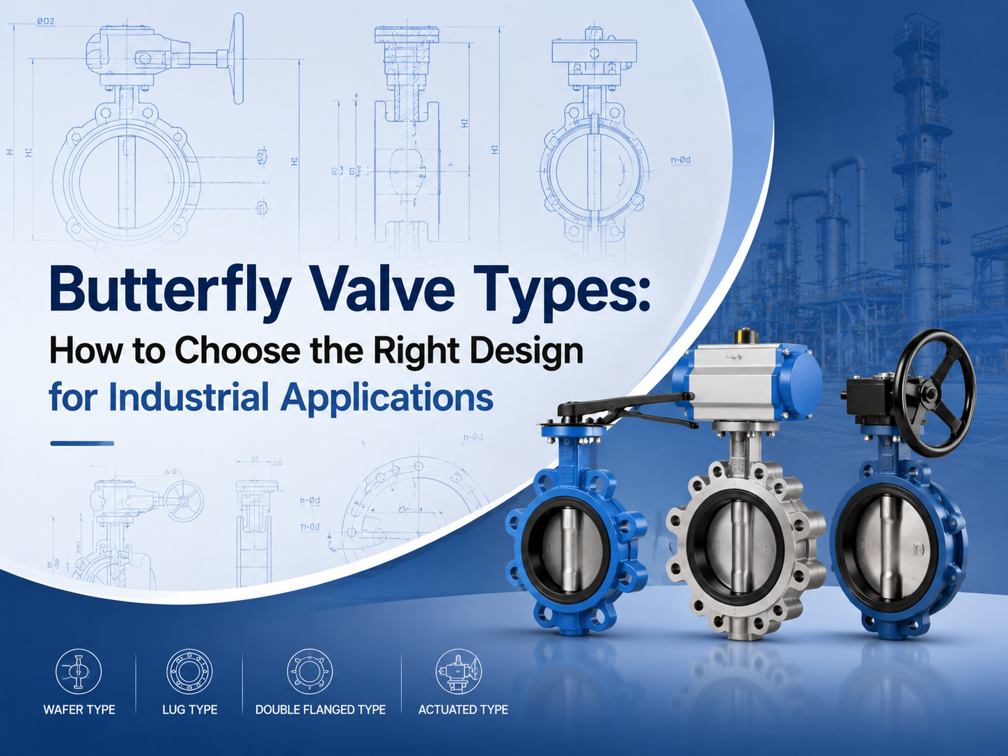
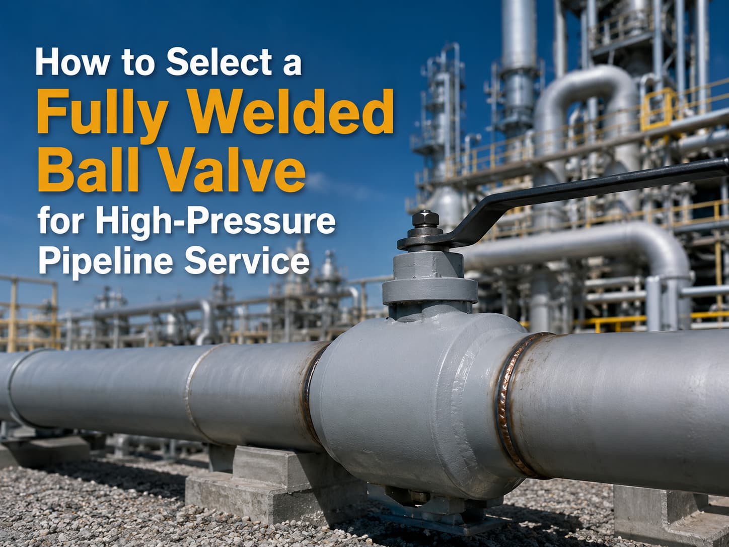
The main butterfly valve types include concentric, double offset, triple offset, wafer, lug, flanged, soft-seated, metal-seated, manual, pneumatic, and electric butterfly valves. The right choice depends on pressure, temperature, media, leakage requirement, installation space, and operation frequency. What Are the Main Butterfly Valve Types? Butterfly valves are usually classified by disc design, body connection, seat material, and actuation method. This classification is important because two valves may both be called butterfly valves, but their service limits can be very different. A butterfly valve uses a rotating disc to isolate or regulate flow. Because of its compact structure, light weight, and quarter-turn operation, it is widely used in water treatment, power plants, chemical processing, HVAC, marine systems, and general industrial pipelines. For buyers, the key question is not simply “which type is cheaper?” It is “which type can handle the actual pressure, temperature, media, and sealing requirement?” Concentric Butterfly Valve A concentric butterfly valve has the stem located on the centerline of the valve body and disc. It is also called a centerline butterfly valve. This type is commonly used for low-pressure and general-service applications, especially with water, air, and non-aggressive fluids. It is simple, economical, and easy to maintain. The limitation is seat wear. During opening and closing, the disc stays in contact with the soft seat for much of its movement. For higher pressure, higher temperature, or stricter shutoff requirements, double offset or triple offset designs are often more suitable. Double Offset Butterfly Valve A double offset butterfly valve uses two offsets to reduce friction between the disc and seat. This improves sealing performance and helps extend service life compared with a basic concentric design. Double offset butterfly valves are often selected for medium-pressure industrial service, including oil and gas, water supply, power generation, and chemical systems. They are useful when the application needs better durability but does not require a full metal-seated triple offset design. This type is also commonly called a high-performance butterfly valve. Before selection, buyers should confirm the pressure class, seat material, shaft sealing design, and expected operation frequency. Triple Offset Butterfly Valve A triple offset butterfly valve adds a third geometric offset to create a more advanced sealing structure. It is typically used for high-temperature, high-pressure, or severe-service applications. The design reduces rubbing between the sealing surfaces during operation. Many triple offset butterfly valves use metal seats, making them suitable for steam, oil and gas, chemical, and other demanding media. For these applications, standards and testing matter. Buyers often need t...
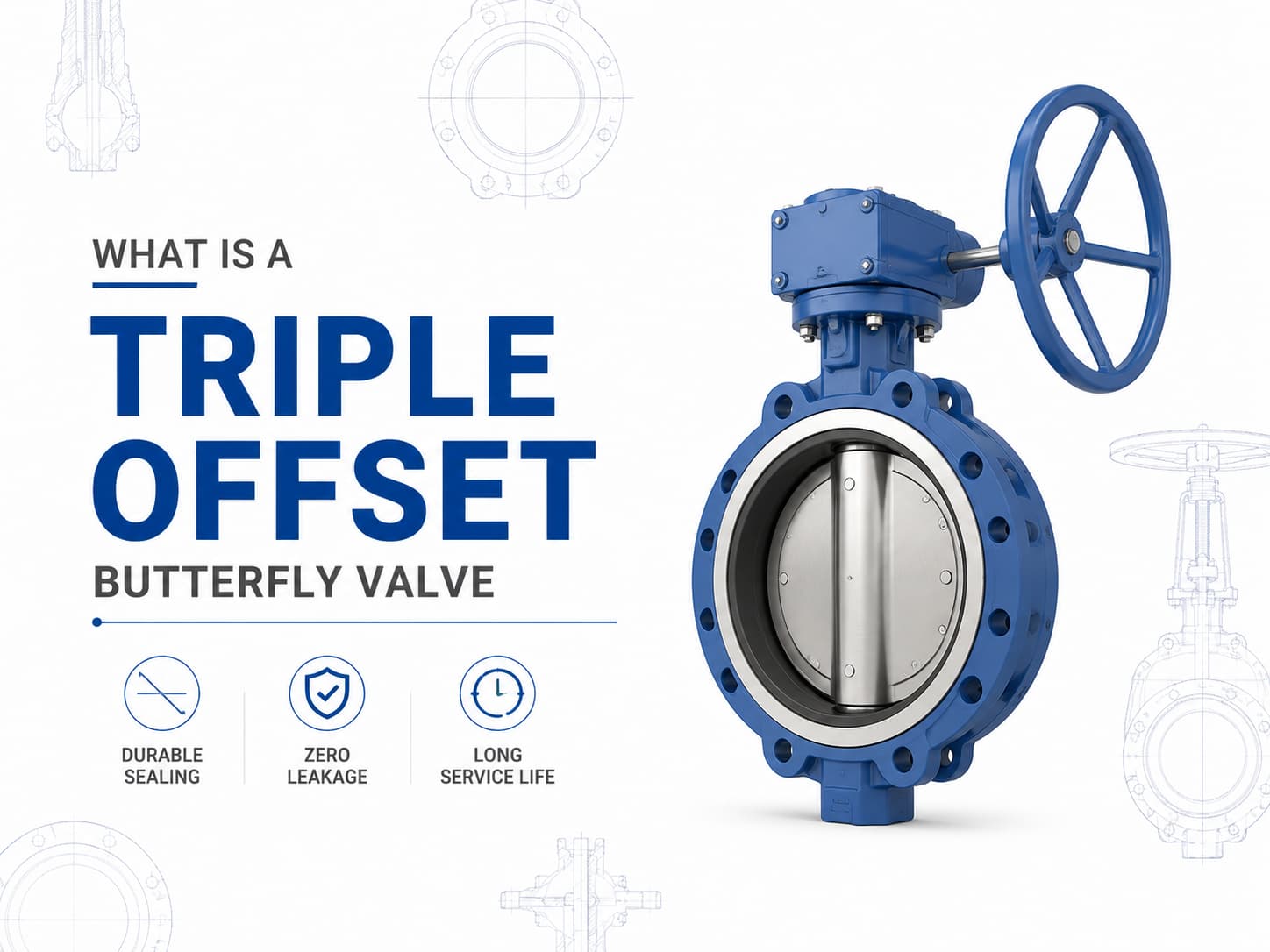
A triple offset butterfly valve is a high-performance isolation valve designed for applications where conventional resilient-seated or double offset butterfly valves cannot meet pressure, temperature, or leakage requirements. By using a three-offset sealing design, the valve achieves a metal-to-metal sealing mechanism with reduced friction between the disc and seat during operation, making it suitable for demanding services such as oil and gas, petrochemical, power generation, LNG, steam, and industrial process systems. Triple Offset Butterfly Valve Design and Working Principle Unlike a concentric butterfly valve, where the shaft is positioned at the centerline of the disc and seat, a triple offset butterfly valve incorporates three independent geometric offsets. The first offset moves the shaft away from the centerline of the valve body, the second offset shifts the shaft from the pipeline centerline, and the third offset introduces a conical sealing surface instead of a circular sealing profile. This geometry allows the disc to move away from the seat immediately after rotation begins, eliminating rubbing between sealing surfaces. The main advantage of this design is that the sealing force is generated by torque rather than continuous compression of soft materials. If the application requires high-temperature service, then a metal-seated triple offset butterfly valve is often preferred because elastomer seats may degrade under elevated temperatures. If the medium contains abrasive particles or aggressive chemicals, then material selection for the disc, seat, and body becomes critical to prevent erosion, corrosion, and leakage during long-term operation. Triple Offset Butterfly Valve Standards and Materials A triple offset butterfly valve is commonly manufactured according to standards such as API 609, EN 593, and ISO 5752, with pressure ratings ranging from Class 150 to Class 600 and higher depending on design requirements. Typical materials include carbon steel, stainless steel, duplex stainless steel, aluminum bronze, and nickel-based alloys. For corrosive seawater applications, aluminum bronze alloys such as C95500 or C95800 may be selected, while sour service applications may require materials compliant with NACE MR0175/ISO 15156 requirements. Triple Offset Butterfly Valve Sealing Performance and Leakage Control The sealing performance of a triple offset butterfly valve depends on the interaction between the sealing ring, seat surface finish, operating torque, and material compatibility. Since the sealing surfaces contact only at the final closing position, mechanical wear is significantly reduced compared with traditional butterfly valve designs. If zero leakage is required for critical isolation, then the valve design, pressure class, and applicable leakage standard, such as API 598 or ISO 5208, must be considered during specification. Triple Offset Butterfly Valve Applications and S...

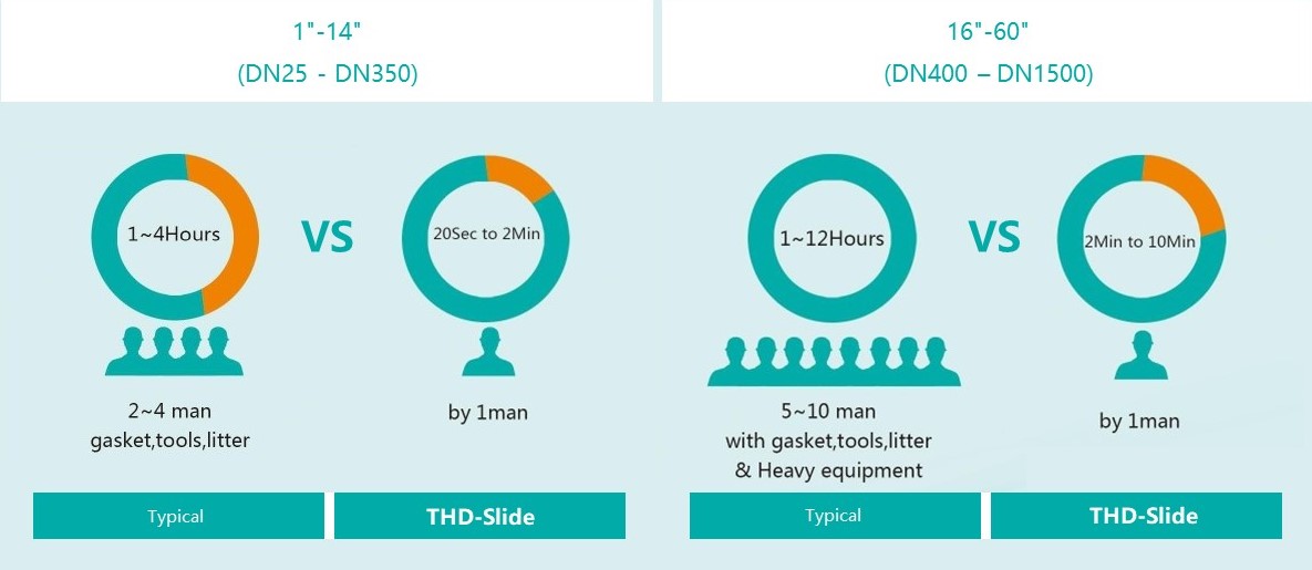
Line blinds are utilized in pipeline systems when there is a need for either complete closure or unimpeded flow transition without a significant drop in pressure. The THD (Through-Hole Design) enables swift and seamless adjustments in position. The THD-slide variant boasts a multi-bolt configuration, making it easier to operate with reduced face-to-face dimensions. The inclusion of extra body bolts renders this style particularly well-suited for high-pressure applications.
Payment:
30% when order confirmed, 70% before shipmentProduct Origin:
ChinaColor:
CustomizationShipping Port:
Shanghai, ChinaLead Time:
30~60 days Ex Works after order confirmationFeatures
1. Swift Transition: Blinding can be performed safely in a matter of minutes, even by operators with minimal experience.
2. Economical Solution: Decreases maintenance hours, resulting in savings on labor costs.
3. Toolless Handling: The process is simplified with a hand-wheel operation, eliminating the need for tools to achieve full shut-off.
Standard Specifications
|
Size |
1'' - 60'' (DN 25 to DN 1500) |
|
Pressure Class |
Class 150 - 2500 (PN 2.5 to PN 400) |
|
Design & Manufacture code |
ASME B16.34 |
|
Flange Standard |
ASME B16.5 |
|
Material |
Carbon Steel, Stainless Steel, Hastelloy, and Titanium |
|
Actuation |
Manual, Pneumatic Hydraulic and Electric |
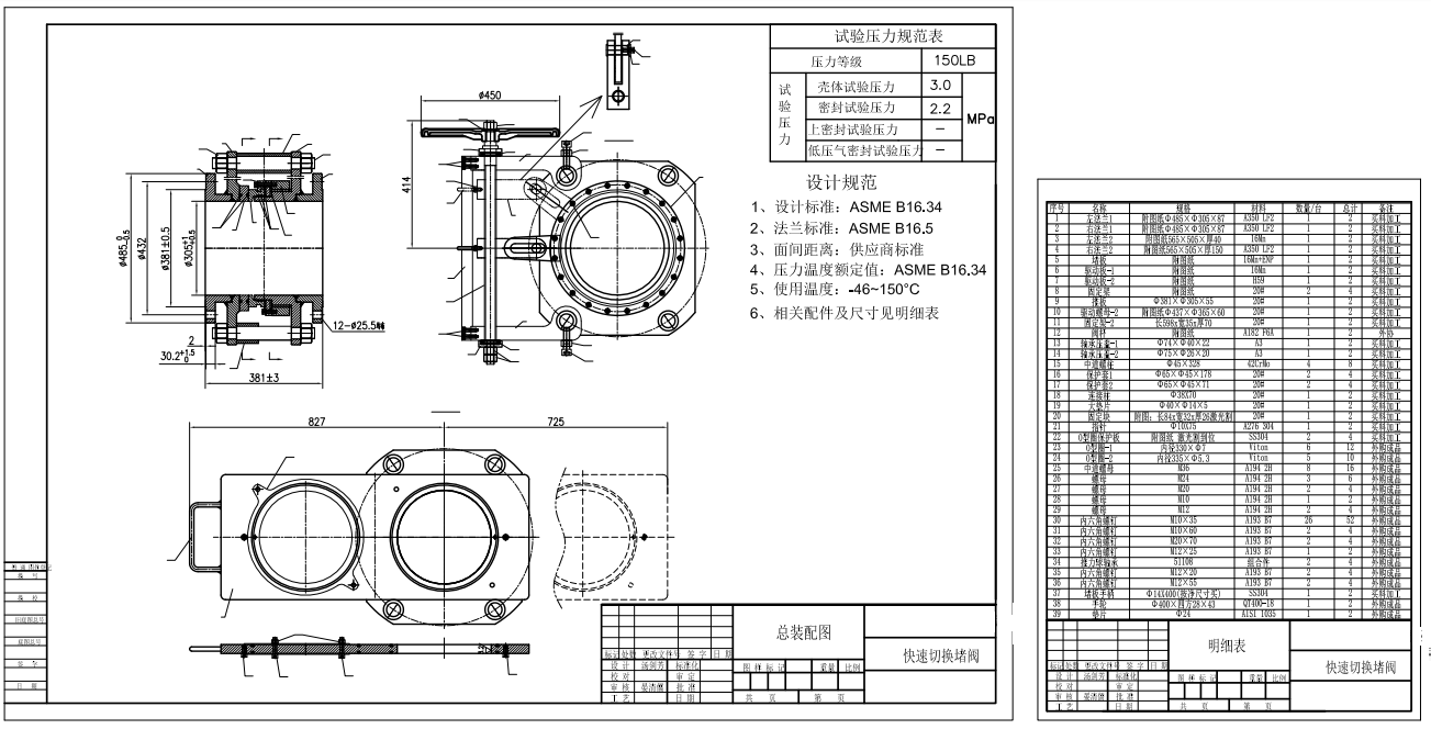
Technical Drawing
Adaptable Design
In addition to its conventional design, the THD-Slide is available in variations tailored for High-Temperature, Fire Safety, and Non-Drip applications. For installations constrained by limited space, a compact version can be provided as well.
Easy Seal Inspection
In this design, the seals are housed within the spectacle plate. This characteristic offers the advantage of convenient access for inspection and seal replacement. Assessing the condition of these seals can be performed external to the operational process, prior to any position changes, thereby ensuring the integrity of the seal's quality.
Cost Effectiveness
The THD-Slide features a straightforward and robust design engineered to deliver complete shutdown, extended operational lifespan, and cost-effective service with minimal maintenance requirements. The distinctive mechanism for opening and closing the THD-Slide enables a single individual to rapidly and safely blind pipelines without the need for any tools or equipment.
THD-Slide Cutout
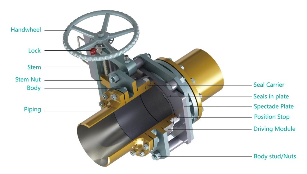
Part Description
|
Part Description |
Material |
|
Handwheel |
QT400-18 |
|
Stem |
A182 F6A |
|
Stem Nut |
Alloy Copper |
|
Body |
A350 LF2 |
|
Seal Carrier |
A350 LF2 |
|
Seals in plate |
Viton |
|
Spectade Plate |
A350 LF2+ENP |
|
Position Stop |
A193 B7 |
|
Driving module |
A350 LF2 |
|
Body stud/Nuts |
A193 B7/A194 2H |
|
Other materials and seal rings are available upon request |
|
Options
●Hand Wheel Extensions
●Locking Device
●Limit Switches
●Drain/Vent ports
●Spectacle Plate Covers to Protect Seals
●Compact Design (integral tapped end flange)
●Rain/Dust Shield
●Torque Limiter
Operation of Standard
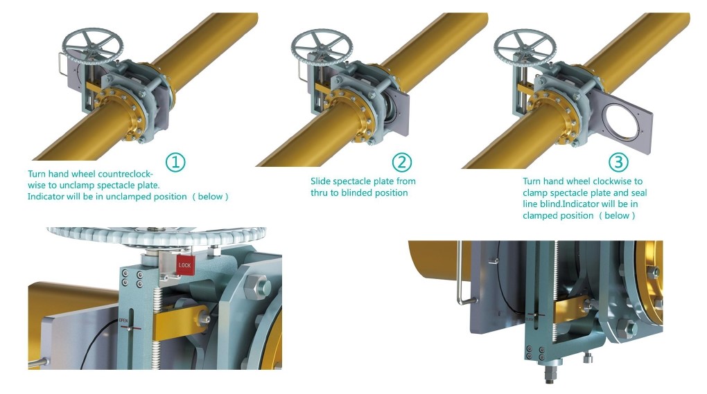
Mechanism Principle
In normal conditions, the blind valve's diversion hole is in contact with the pipeline, and the blind valve is in the open position. When maintenance is required, and the pipeline must be cut off, then loosen the stem of blind valve to move the flat end onto the pipeline, and make the blind valve turn to closed position from open position; tighten the stem and let the blind valve to perform sealing function and cut off the pipeline.
When the maintenance work is completed, loosen the stem and move the blind plate to the diversion hole and connected to the pipeline. The blind valve was turned to closed position from open one. Lock the stem, and seal it, the pipeline is now open, and the blind plate valve returns to the open position.
If you are interested in our products and want to know more details,please leave a message here,we will reply you as soon as we can.
Line blind valve (eyeglass valve) is a kind of gate valve that cuts off gas medium manually, electrically or pneumatically or hydraulically. It is generally divided into electric blind valve, hydraulic blind valve, closed plug valve and electric open blind valve.
10" 150LB line blind valve is made according to ASME B16.34 standard. The valve body is made of A105. It has the structural characteristics of anti-drip. Its connection mode is RF. And it has turbine operation mode.
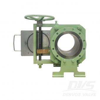
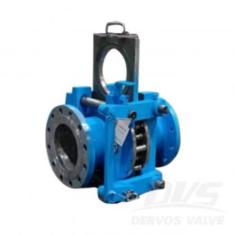
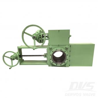
This DN400 PN40 forged slide blind valve provides positive isolation for steam pipelines and high-temperature industrial systems—physically blocking flow with a solid blind plate to ensure zero leakage during maintenance. Unlike conventional valves that rely on seats that can wear or degrade, this blind valve creates an absolute physical barrier, protecting personnel and preventing costly shutdowns. The sliding blind mechanism enables operators to switch between flow and isolation positions without depressurizing the line, significantly reducing downtime. Constructed from a one-piece forged A182 LF2 steel body, it delivers exceptional low-temperature toughness (down to -46°C) and reliable performance under PN40 pressure and high-temperature steam service up to 350°C. Designed to EN12516-1/2 and 100% pressure tested to EN12266-1/2, this valve features RF flanges per GOST 33259-Type B and a gear operator for smooth, high-torque actuation on large-diameter lines. It is a trusted choice for refineries, power plants, and industrial pipeline isolation where safety and reliability are paramount. Product Parameters Type Slide Blind Valve Size DN400 Pressure PN40 Connection RF Operation GEAR Body Material A182 LF2 Design Norm EN12516-1/2 Face to face Supplier Standards Flange dimension GOST 33259-Type B Test & Inspection Code EN12266-1/2 Temperature -46 ~ 350°C Applicable Medium Water, Oil and Gas Features • True Physical Barrier – Zero Leakage Isolation– Solid blind plate creates a true physical barrier. The one-piece forged LF2 body eliminates weld seams, ensuring structural integrity under PN40 pressure and thermal cycling. • Inline Operation Without Depressurization – Sliding mechanism enables switching without system blowdown. LF2 steel ensures reliable operation down to -46°C, ideal for cold climates and cryogenic steam conditions. • Gear-Operated for Large Diameters – High-torque gearbox ensures smooth and controlled operation for DN400 valves, even under demanding conditions. • Low-Temperature Toughness – ASTM A182 LF2 forged steel ensures reliable operation down to -46°C, ideal for cold climates and cryogenic steam conditions. Sliding Type Line Blind Valve Technical Drawing Dimension Checking Pressure Testing Painting Nameplate & Packing Inspection Report
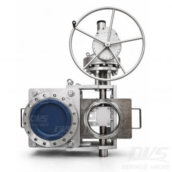
This 10-inch Class 150 Sliding Line Blind Valve provides absolute positive isolation for steam turbine pipelines and high-temperature industrial systems. Unlike conventional gate or ball valves that rely on seats subject to wear, the sliding blind mechanism creates a solid physical barrier—delivering zero leakage during maintenance and ensuring personnel safety. The gear-operated sliding plate allows operators to switch between flow and isolation positions without depressurizing the line, significantly reducing downtime. The drip-proof design prevents fugitive emissions, making it ideal for steam, oil, gas, and other critical services. Constructed from ASTM A105 forged carbon steel with RF flanges per ASME B16.5, the valve is designed to ASME B16.34 and tested to API 598. It offers reliable performance in applications up to 425°C (sealing dependent), combining durability, safety, and ease of operation. Product Parameters Type Sliding Blind Valve Size 10” Pressure 150LB Connection RF Operation Turbine Body Material A105 Design Norm ASME B16.34 Face to face Manufacturer Standard Flange dimension ASME B16.5 Test & Inspection Code API 598 Temperature -29 ~ 150°C (Higher temperature up to 425°C available with metal seat) Applicable Medium Water, Oil and Gas Features • Forged A105 Carbon Steel Body – Provides strength and durability for reliable performance in industrial pipeline service. • Drip-Proof Design – Prevents fugitive emissions and protects internal components, making it ideal for environmentally sensitive applications and steam turbine systems. • Absolute Physical Isolation – Solid blind plate provides true physical separation of the pipeline, ensuring safe maintenance without relying on sealing surfaces. • Online Switching – No Depressurization Required – Sliding mechanism allows switching between open and blind positions without pipeline blowdown, reducing downtime and media loss. • Gear-Operated for Large Diameters – High-torque turbine drive enables smooth and controlled operation for large valves, even under demanding conditions. Slide Type Line Blind Valve Technical Drawing Dimension Checking Pressure Testing Painting Nameplate & Packing Inspection Report
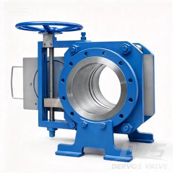
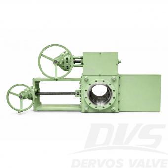
Introduction This 10" Class 300 Sliding Line Blind Valve provides absolute positive isolation for medium‑ to high‑pressure pipelines, combining the reliability of a solid physical barrier with the simplicity of manual screw‑operated actuation. Unlike conventional valves that rely on seats prone to wear, the sliding blind mechanism creates a true physical barrier, ensuring zero leakage during maintenance without the need for system depressurization. This significantly reduces downtime and enhances personnel safety. The manual screw‑operated design offers precise, controlled movement of the blind plate, with inherent self‑locking capability to maintain position under pressure—ideal for applications where electric or pneumatic power may not be available or preferred. Constructed to ASME B16.34 with RF flanges per ASME B16.5, this valve is available in forged carbon steel (A105), stainless steel, or alloy materials to suit your service conditions. Each unit is 100% pressure tested to API 598. This 10" Class 300 configuration is a popular choice for steam, oil, gas, and chemical pipelines. Other sizes from 1" to 60" and pressure classes up to Class 2500 are available as part of our full line blind valve series. THD-Slide Cutout Features 1.Manual Screw‑Operated with Self‑Locking Precision screw drive allows smooth, controlled positioning of the blind plate. The self‑locking mechanism maintains position under pressure without additional braking devices. 2.Absolute Physical Isolation Solid blind plate creates a true barrier, ensuring zero leakage during maintenance—unlike seat‑dependent valves that can wear or degrade over time. 3.Inline Operation Without Depressurization Sliding mechanism enables switching between flow and blind positions without system blowdown, reducing downtime and product loss. 4.10″ Class 300 – The Optimal Balance Offers higher pressure capability than Class 150 while remaining more economical than Class 600, making it a versatile choice for a wide range of industrial applications. 5.Forged Carbon Steel Construction A105 forged body provides high strength, impact resistance, and reliable performance under thermal cycling. 6.Tested to API 598 100% hydrostatic and pneumatic testing ensures leak‑tight performance before shipment. Standard Specifications Parameter Specification Type Sliding Line Blind Valve Size 10″ (DN250) Pressure Rating Class 300 (PN50) Connection RF Flange, ASME B16.5 Operation Manual Screw-Operated (Self-locking) Body Material A105 Forged Carbon Steel (other alloys available) Seal / Seat Material Metal-to-Metal (Stainless Steel + Graphite) Design Standard ASME B16.34 Face-to-Face Dimension Per ASME B16.10 or manufacturer standard Test & Inspection API 598 (100% hydrostatic & pneumatic) Temperature Range -29°C to +425°C (depending on sealing) Applicable Media Steam, Oil, Gas, Water, Hydrocarbons Application Pipeline isolation, refineries, petrochemical plants, power generation Technical Drawing Flexible Design Options Tailored Configurations for Demanding Applications Beyond the base model, this line blind valve can be customized for high-temperature service, fire-safe requirements, and zero-emission (drip-proof) operation. For installations where space is at a premium, a compact variant is available, offering the same robust isolation performance in a reduced footprint. Simplified Seal Maintenance– No Disassembly Required Seals are integrated into the spectacle plate, allowing operators to inspect or replace them without dismantling the valve. Condition checks can be performed while the valve remains in service, before any position change, ensuring seal integrity is verified before operation. Low Total Cost of Ownership The valve’s streamlined, heavy‑duty construction delivers reliable positive shut‑off with minimal upkeep. Its unique actuation mechanism allows a single operator to quickly and safely isolate the pipeline—no tools required—reducing labor time and simplifying maintenance procedures. Options ●Hand Wheel Extensions ●Locking Device ●Limit Switches ●Drain/Vent ports ●Spectacle Plate Covers to Protect Seals ●Compact Design (integral tapped end flange) ●Rain/Dust Shield ●Torque Limiter
Copyright © 2015-2026 DERVOS VALVE CO.,LTD.All Rights Reserved Blog / Sitemap / XML / Privacy Policy