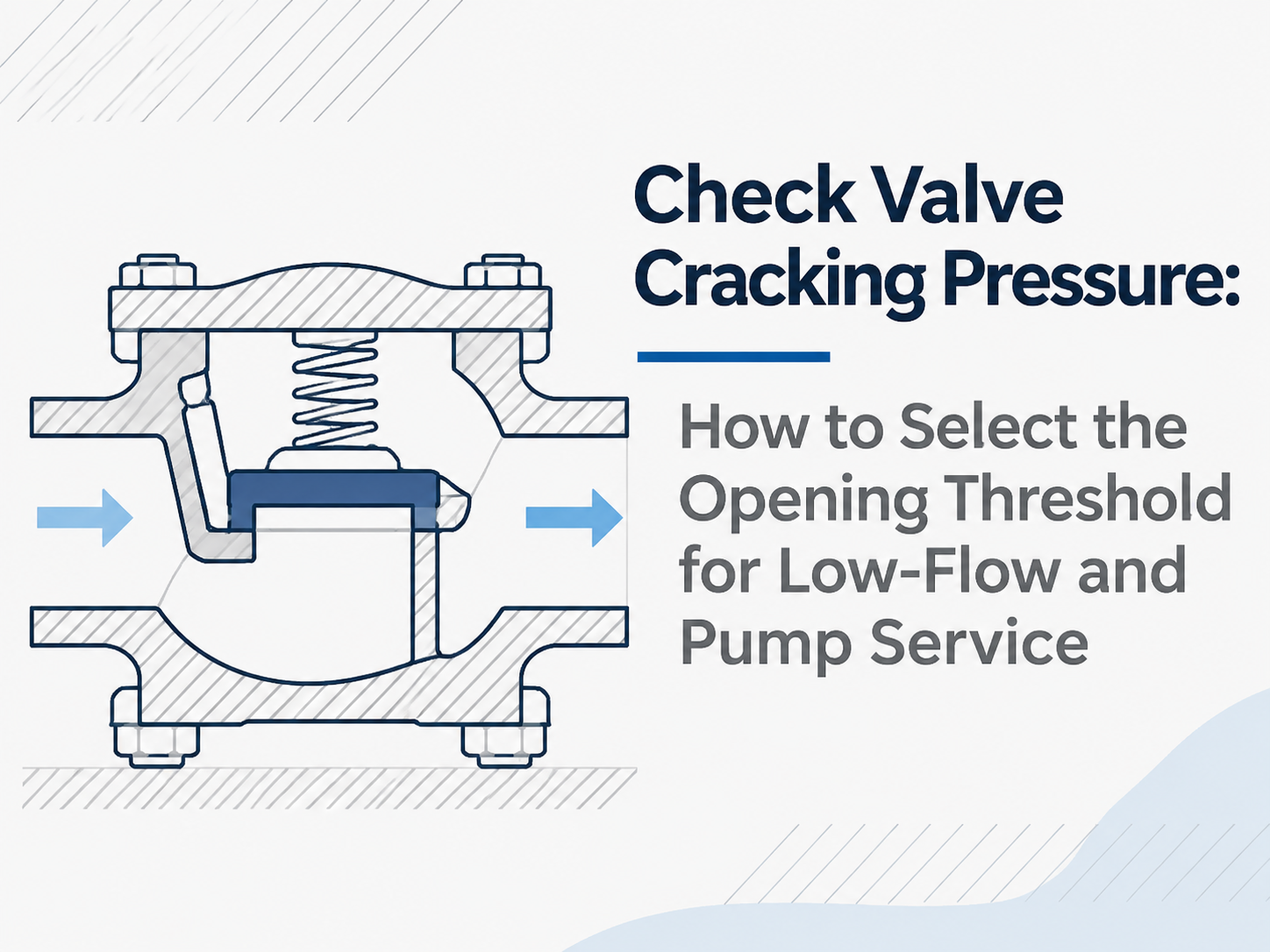
A check valve can begin to pass fluid and still be far from a stable open position. Check valve cracking pressure is therefore the threshold for first detectable flow, not the full-open pressure drop or proof of reliable minimum-flow operation. For low-flow and pump service, the opening threshold is acceptable only when the system can exceed it in the worst forward-flow case. The selection must then pass three separate checks: stable valve travel at minimum flow, acceptable pressure loss at normal and maximum flow, and timely closure when the pump stops. Start with the Worst Available Differential Pressure Parker defines cracking pressure as the upstream pressure at which detectable flow is measured, while Swagelok notes that first flow does not mean the valve is fully open. The relevant system value is not pump discharge pressure alone, but the pressure difference across the valve when it must open. For an initial screen: Available opening ΔP = minimum upstream pressure at the valve − maximum downstream pressure at the valve If the pressures come from remote points, correct them for elevation and line losses. Evaluate the least favorable credible case, such as a variable-speed pump starting at low speed or a standby pump opening against a live common header. The maximum guaranteed cracking pressure of the offered valve should be below this available ΔP, with an engineering allowance for manufacturing tolerance, temperature, orientation, deposits and measurement uncertainty. There is no defensible universal allowance. A nominal value alone is insufficient because catalog cracking pressure may be specified as a range, and a valve left idle may initially require a higher differential than it does after cycling. Low Cracking Pressure Does Not Solve Low-Flow Instability After the closure member lifts, more differential pressure and flow force are needed for stable travel. An oversized valve may crack open but hover near the seat because velocity is too low, causing clicking, flutter, impact and accelerated wear. Swagelok’s service guidance identifies excessive spring cracking pressure and excessive valve size as possible causes of chatter near the threshold. Size from the operating envelope rather than automatically matching the pipe diameter. Ask the supplier to evaluate three points for the exact size, spring and trim: Operating point Required evidence Minimum continuous flow Stable-open position, minimum stable flow or velocity, and corresponding ΔP Normal flow Model-specific pressure-drop curve or validated flow coefficient Maximum flow Peak ΔP, velocity limits, erosion risk and acceptable travel Cracking pressure answers “When does motion begin?” The flow curve and stable-flow limit answer “Will the valve remain open without damaging itself?” Pump Opening and Pump Shutdown Are Different Design Cases At s...
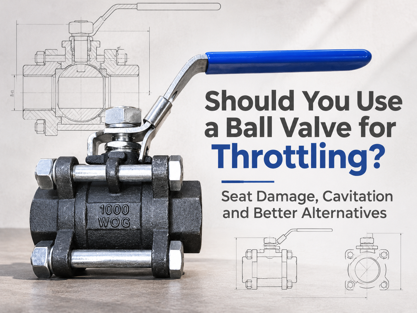
A standard on-off ball valve should not be the default choice for continuous throttling. It can restrict flow, but that does not make it a control valve. Holding it partly open can expose the seat to a concentrated high-velocity jet, produce unstable control and, in liquid service, create cavitation. Brief restriction during start-up or shutdown may be acceptable if the manufacturer permits it. Regular modulation requires a valve designed and sized for that duty. A Part-Open Ball Puts the Seat in the Flow Path When a standard ball valve is fully open, the bore provides a relatively straight flow path. As the ball rotates toward closed, the opening becomes a narrow, changing shape. Velocity rises through this restriction, and the emerging jet can pass close to the downstream seat edge and body cavity. That matters because the seat performs the shutoff function. A soft seat may deform, cut or erode under high velocity, heat and entrained solids. A metal seat may tolerate harsher conditions, but hardness alone does not provide a suitable control characteristic or prevent local erosion. Damage often appears later as increased shutoff leakage, even though the valve still moves normally. Control quality is another limitation. A conventional full-port ball may pass a large increase in flow over a small change in travel once it begins to open. The actuator can therefore hunt around a narrow angle instead of positioning smoothly across a useful range. A positioner cannot correct an unsuitable valve characteristic. Cavitation Depends on the Local Pressure, Not Just Line Pressure Cavitation is possible when liquid accelerates through the restriction and its local pressure falls below the liquid's vapour pressure. Vapour bubbles then form. If pressure recovers above vapour pressure downstream, the bubbles collapse and release damaging energy near the valve or downstream pipe. Ball valves are generally high-recovery valves: much of the pressure lost at the narrowest flow area is recovered downstream. That means the minimum internal pressure can be considerably lower than the measured outlet pressure. A moderate-looking inlet-to-outlet pressure drop may therefore hide a more severe pressure dip inside the valve. Noise resembling gravel, vibration and rough pitting are warning signs, but sound alone is not a design method. The evaluation needs minimum, normal and maximum flow; upstream and downstream pressure at each case; fluid temperature and vapour pressure; density; solids content; valve size; and the manufacturer's pressure-recovery and sizing data. If downstream pressure remains below vapour pressure, the condition is flashing rather than cavitation and requires a different damage assessment. A Ball Valve Can Throttle When It Is a Control Valve A V-port or segmented ball introduces a shaped opening that gives a more predictable relationship between travel and flow. Correctly sele...
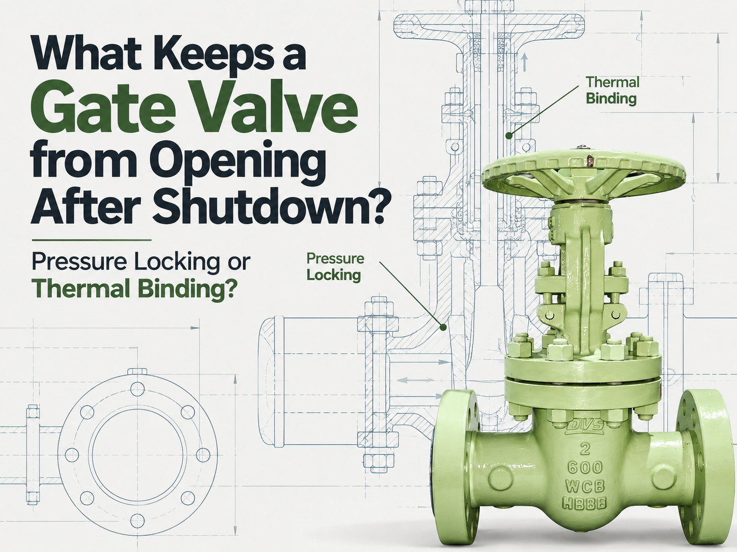
A gate valve that will not open after shutdown may be pressure locked or thermally bound, and the shutdown history usually separates the two. Pressure locking means pressure is trapped in the bonnet cavity; thermal binding means a hot-closed wedge has developed mechanical interference during cooldown. Neither is an automatic reason to raise the actuator torque setting. Pressure Locking Starts in the Bonnet Cavity Pressure locking can affect flexible-wedge and double-disc gate valves when liquid enters the bonnet cavity during operation or through slight seat movement or leakage. Once the valve is closed, that liquid may be trapped between the two seating boundaries. The problem develops when cavity pressure exceeds the pressure on both sides of the closed gate. The line may have been depressurised after the cavity filled at operating pressure, or trapped liquid may have heated and expanded. The resulting load forces the closure element against both seats, leaving normal actuator thrust insufficient to start opening. A failed opening after line depressurisation, or after the closed valve was heated, points toward pressure locking. Where an approved connection permits measurement, bonnet pressure is stronger evidence than high motor current or a torque trip alone. Thermal Binding Follows Hot Closure and Cooldown Thermal binding follows a different sequence. A wedge gate valve is seated hot and the system cools before the next opening command. Unequal contraction of the body and wedge can increase mechanical interference at the seats. Solid wedges are particularly susceptible, although large temperature changes can also affect flexible wedges. This mechanism does not require an overpressurised cavity. Its strongest clue is timing: the valve closes normally at operating temperature but refuses to open after cooldown. Behaviour that changes as temperature returns toward the closing condition supports the diagnosis, but deliberate reheating requires an approved procedure. Uncontrolled external heating is unsafe. Reconstruct the Shutdown Before Touching the Torque Switch Start with the pressure and temperature timeline. Record when the valve closed, whether either side was later drained or depressurised, whether the body remained exposed to heat, and the temperature at the failed opening attempt. Confirm the gate design from drawings or manufacturer records; solid-wedge, flexible-wedge and double-disc designs do not share the same susceptibility. Rule out ordinary faults such as lost power or pressure, wrong limit or torque-switch settings, stem or packing friction, gearbox damage, corrosion and debris. Actuator alarms and the point where movement stopped help distinguish a drive problem from a gate held at the seats. Do not bypass the torque switch or repeatedly hammer the valve open. Extra thrust may bend the stem, damage the seats or overload the gearbox. A larger actuator d...
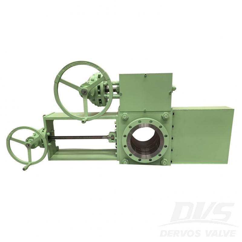
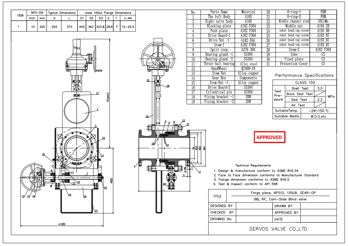
10" 150LB line blind valve is made according to ASME B16.34 standard. The valve body is made of A105. It has the structural characteristics of anti-drip. Its connection mode is RF. And it has turbine operation mode.
Payment:
30% when order confirmed, 70% before shipmentProduct Origin:
ChinaColor:
CustomizationShipping Port:
Shanghai, ChinaLead Time:
30~60 days Ex Works after order confirmationMaterial:
A105Method of Operation:
Turbine Operation
|
Type |
Line Blind Valve |
|
Size |
10" |
|
Pressure |
150LB |
|
Connection |
RF |
|
Operation |
Worm Gear Operated |
|
Body Material |
A105 |
|
Design Norm |
ASME B16.34 |
|
Face to Face Dimension |
Manufacturer Standard |
|
Flange Dimension |
ASME B16.5 |
|
Test & Inspection Code |
API 598 |
|
Temperature |
-29 ~ 150°C |
|
Applicable Medium |
Water, Oil and Gas |
1. Equipped with quick opening and closing function, no additional disassembly or installation of pipe fittings is required, reducing operation time and worker workload;
2. Suitable for various media, including gases, liquids, slurries, and particulate matter, widely used in industries such as petrochemicals, metallurgy, and power.
If you are interested in our products and want to know more details,please leave a message here,we will reply you as soon as we can.
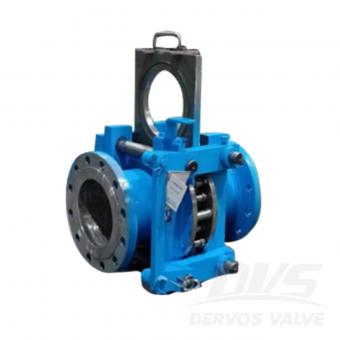
Line blind valve (eyeglass valve) is a kind of gate valve that cuts off gas medium manually, electrically or pneumatically or hydraulically. It is generally divided into electric blind valve, hydraulic blind valve, closed plug valve and electric open blind valve.
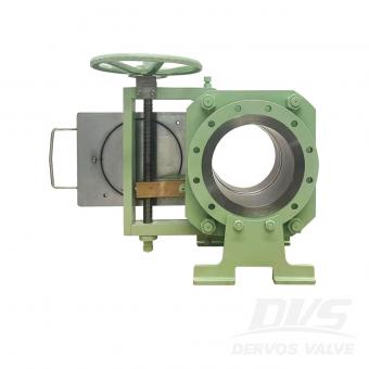
Line blinds are utilized in pipeline systems when there is a need for either complete closure or unimpeded flow transition without a significant drop in pressure. The THD (Through-Hole Design) enables swift and seamless adjustments in position. The THD-slide variant boasts a multi-bolt configuration, making it easier to operate with reduced face-to-face dimensions. The inclusion of extra body bolts renders this style particularly well-suited for high-pressure applications.
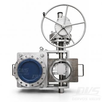
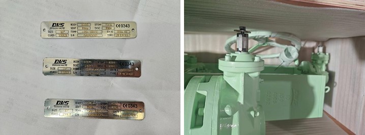
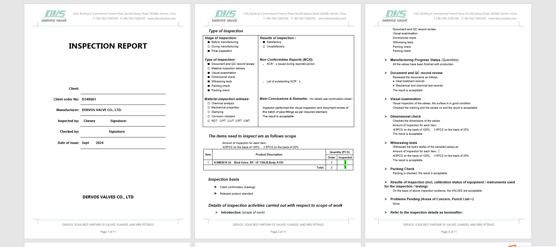
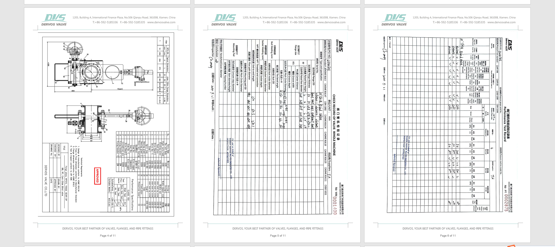
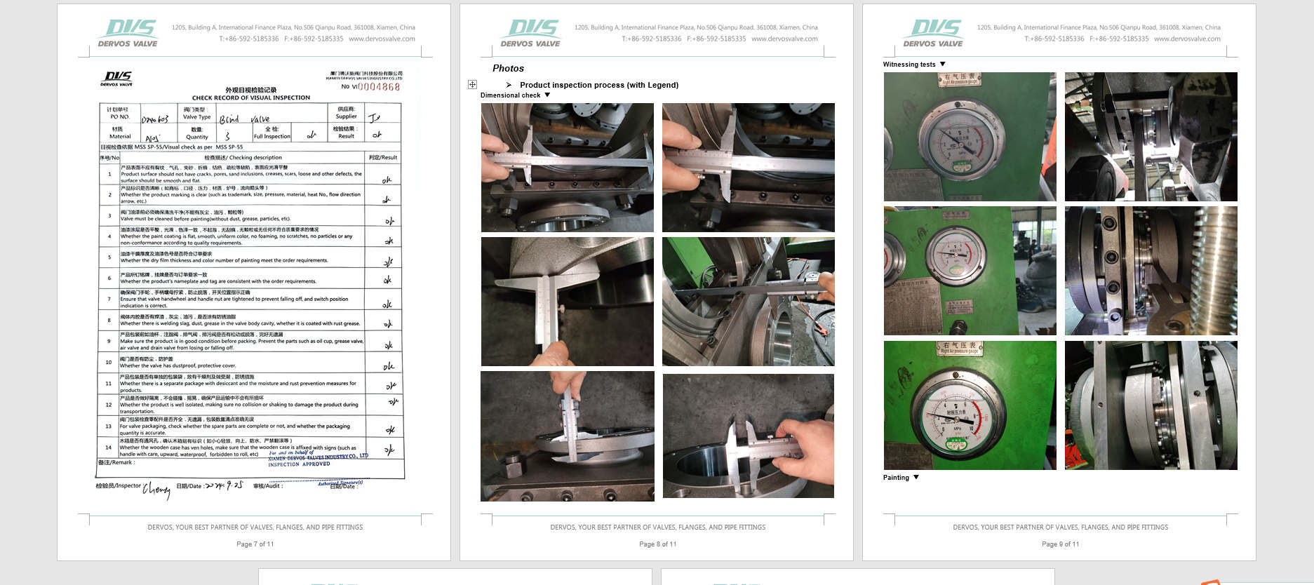
This DN400 PN40 forged slide blind valve provides positive isolation for steam pipelines and high-temperature industrial systems—physically blocking flow with a solid blind plate to ensure zero leakage during maintenance. Unlike conventional valves that rely on seats that can wear or degrade, this blind valve creates an absolute physical barrier, protecting personnel and preventing costly shutdowns. The sliding blind mechanism enables operators to switch between flow and isolation positions without depressurizing the line, significantly reducing downtime. Constructed from a one-piece forged A182 LF2 steel body, it delivers exceptional low-temperature toughness (down to -46°C) and reliable performance under PN40 pressure and high-temperature steam service up to 350°C. Designed to EN12516-1/2 and 100% pressure tested to EN12266-1/2, this valve features RF flanges per GOST 33259-Type B and a gear operator for smooth, high-torque actuation on large-diameter lines. It is a trusted choice for refineries, power plants, and industrial pipeline isolation where safety and reliability are paramount. Product Parameters Type Slide Blind Valve Size DN400 Pressure PN40 Connection RF Operation GEAR Body Material A182 LF2 Design Norm EN12516-1/2 Face to face Supplier Standards Flange dimension GOST 33259-Type B Test & Inspection Code EN12266-1/2 Temperature -46 ~ 350°C Applicable Medium Water, Oil and Gas Features • True Physical Barrier – Zero Leakage Isolation– Solid blind plate creates a true physical barrier. The one-piece forged LF2 body eliminates weld seams, ensuring structural integrity under PN40 pressure and thermal cycling. • Inline Operation Without Depressurization – Sliding mechanism enables switching without system blowdown. LF2 steel ensures reliable operation down to -46°C, ideal for cold climates and cryogenic steam conditions. • Gear-Operated for Large Diameters – High-torque gearbox ensures smooth and controlled operation for DN400 valves, even under demanding conditions. • Low-Temperature Toughness – ASTM A182 LF2 forged steel ensures reliable operation down to -46°C, ideal for cold climates and cryogenic steam conditions. Sliding Type Line Blind Valve Technical Drawing Dimension Checking Pressure Testing Painting Nameplate & Packing Inspection Report
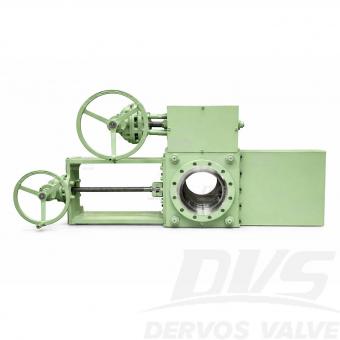
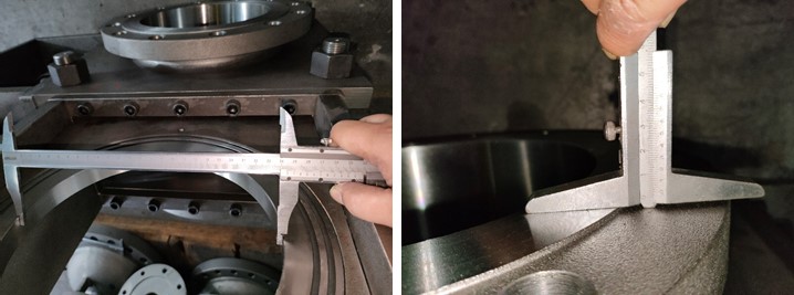
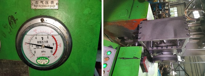
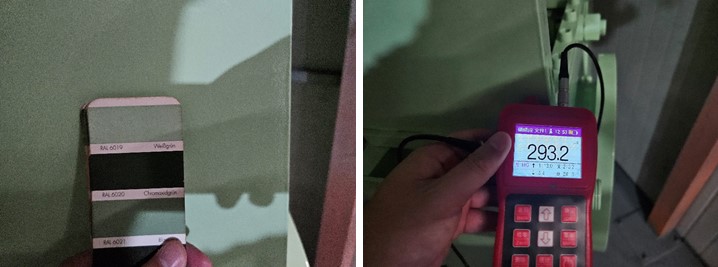
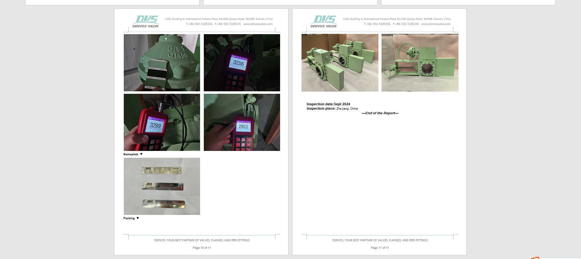
This 10-inch Class 150 Sliding Line Blind Valve provides absolute positive isolation for steam turbine pipelines and high-temperature industrial systems. Unlike conventional gate or ball valves that rely on seats subject to wear, the sliding blind mechanism creates a solid physical barrier—delivering zero leakage during maintenance and ensuring personnel safety. The gear-operated sliding plate allows operators to switch between flow and isolation positions without depressurizing the line, significantly reducing downtime. The drip-proof design prevents fugitive emissions, making it ideal for steam, oil, gas, and other critical services. Constructed from ASTM A105 forged carbon steel with RF flanges per ASME B16.5, the valve is designed to ASME B16.34 and tested to API 598. It offers reliable performance in applications up to 425°C (sealing dependent), combining durability, safety, and ease of operation. Product Parameters Type Sliding Blind Valve Size 10” Pressure 150LB Connection RF Operation Turbine Body Material A105 Design Norm ASME B16.34 Face to face Manufacturer Standard Flange dimension ASME B16.5 Test & Inspection Code API 598 Temperature -29 ~ 150°C (Higher temperature up to 425°C available with metal seat) Applicable Medium Water, Oil and Gas Features • Forged A105 Carbon Steel Body – Provides strength and durability for reliable performance in industrial pipeline service. • Drip-Proof Design – Prevents fugitive emissions and protects internal components, making it ideal for environmentally sensitive applications and steam turbine systems. • Absolute Physical Isolation – Solid blind plate provides true physical separation of the pipeline, ensuring safe maintenance without relying on sealing surfaces. • Online Switching – No Depressurization Required – Sliding mechanism allows switching between open and blind positions without pipeline blowdown, reducing downtime and media loss. • Gear-Operated for Large Diameters – High-torque turbine drive enables smooth and controlled operation for large valves, even under demanding conditions. Slide Type Line Blind Valve Technical Drawing Dimension Checking Pressure Testing Painting Nameplate & Packing Inspection Report
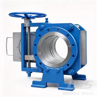
Introduction This 10" Class 300 Sliding Line Blind Valve provides absolute positive isolation for medium‑ to high‑pressure pipelines, combining the reliability of a solid physical barrier with the simplicity of manual screw‑operated actuation. Unlike conventional valves that rely on seats prone to wear, the sliding blind mechanism creates a true physical barrier, ensuring zero leakage during maintenance without the need for system depressurization. This significantly reduces downtime and enhances personnel safety. The manual screw‑operated design offers precise, controlled movement of the blind plate, with inherent self‑locking capability to maintain position under pressure—ideal for applications where electric or pneumatic power may not be available or preferred. Constructed to ASME B16.34 with RF flanges per ASME B16.5, this valve is available in forged carbon steel (A105), stainless steel, or alloy materials to suit your service conditions. Each unit is 100% pressure tested to API 598. This 10" Class 300 configuration is a popular choice for steam, oil, gas, and chemical pipelines. Other sizes from 1" to 60" and pressure classes up to Class 2500 are available as part of our full line blind valve series. THD-Slide Cutout Features 1.Manual Screw‑Operated with Self‑Locking Precision screw drive allows smooth, controlled positioning of the blind plate. The self‑locking mechanism maintains position under pressure without additional braking devices. 2.Absolute Physical Isolation Solid blind plate creates a true barrier, ensuring zero leakage during maintenance—unlike seat‑dependent valves that can wear or degrade over time. 3.Inline Operation Without Depressurization Sliding mechanism enables switching between flow and blind positions without system blowdown, reducing downtime and product loss. 4.10″ Class 300 – The Optimal Balance Offers higher pressure capability than Class 150 while remaining more economical than Class 600, making it a versatile choice for a wide range of industrial applications. 5.Forged Carbon Steel Construction A105 forged body provides high strength, impact resistance, and reliable performance under thermal cycling. 6.Tested to API 598 100% hydrostatic and pneumatic testing ensures leak‑tight performance before shipment. Standard Specifications Parameter Specification Type Sliding Line Blind Valve Size 10″ (DN250) Pressure Rating Class 300 (PN50) Connection RF Flange, ASME B16.5 Operation Manual Screw-Operated (Self-locking) Body Material A105 Forged Carbon Steel (other alloys available) Seal / Seat Material Metal-to-Metal (Stainless Steel + Graphite) Design Standard ASME B16.34 Face-to-Face Dimension Per ASME B16.10 or manufacturer standard Test & Inspection API 598 (100% hydrostatic & pneumatic) Temperature Range -29°C to +425°C (depending on sealing) Applicable Media Steam, Oil, Gas, Water, Hydrocarbons Application Pipeline isolation, refineries, petrochemical plants, power generation Technical Drawing Flexible Design Options Tailored Configurations for Demanding Applications Beyond the base model, this line blind valve can be customized for high-temperature service, fire-safe requirements, and zero-emission (drip-proof) operation. For installations where space is at a premium, a compact variant is available, offering the same robust isolation performance in a reduced footprint. Simplified Seal Maintenance– No Disassembly Required Seals are integrated into the spectacle plate, allowing operators to inspect or replace them without dismantling the valve. Condition checks can be performed while the valve remains in service, before any position change, ensuring seal integrity is verified before operation. Low Total Cost of Ownership The valve’s streamlined, heavy‑duty construction delivers reliable positive shut‑off with minimal upkeep. Its unique actuation mechanism allows a single operator to quickly and safely isolate the pipeline—no tools required—reducing labor time and simplifying maintenance procedures. Options ●Hand Wheel Extensions ●Locking Device ●Limit Switches ●Drain/Vent ports ●Spectacle Plate Covers to Protect Seals ●Compact Design (integral tapped end flange) ●Rain/Dust Shield ●Torque Limiter
Copyright © 2015-2026 DERVOS VALVE CO.,LTD.All Rights Reserved Blog / Sitemap / XML / Privacy Policy