In 2026, DERVOS VALVE proudly celebrates its 18th anniversary, marking an important milestone in the company's journey. To commemorate this occasion, DERVOS VALVE organized a three-day anniversary celebration, bringing together all employees to reflect on the company's achievements over the past eighteen years, look ahead to future development, and further strengthen team cohesion through meaningful activities and shared experiences. Reflecting on 18 Years of Growth From raw material management and precision machining to assembly and product testing, every stage of production reflects DERVOS VALVE's unwavering commitment to quality. Over the past eighteen years, DERVOS VALVE has continuously improved its manufacturing system while enhancing product quality and customer service capabilities. Today, our industrial valves are widely used across the oil and gas, chemical, power generation, water treatment, LNG, and other industrial sectors, providing reliable valve solutions to customers worldwide. Building Consensus for Future Development During the anniversary celebration, DERVOS VALVE also held its mid-year communication meeting. The meeting reviewed the company's performance over the first half of the year and outlined key objectives for future development. Representatives from different departments exchanged insights on production management, quality improvement, and cross-functional collaboration, sharing practical experience, reviewing achievements, and discussing future goals together. The meeting further strengthened communication among departments, reinforced team alignment, and injected new momentum into the company's long-term development. Embracing Nature Together In addition to the company's anniversary activities, DERVOS VALVE organized a group excursion to experience the beauty of nature. Surrounded by picturesque landscapes, employees enjoyed the scenic environment and explored the local culture in a relaxed and enjoyable atmosphere. The trip provided an opportunity to unwind while fostering stronger relationships among colleagues. This memorable experience enriched the anniversary celebration, strengthened team spirit, and inspired everyone with renewed energy for the work ahead. Eighteen Years of Commitment, Looking Ahead Eighteen years represent not only growth and achievement, but also the beginning of a new chapter. Since its establishment, DERVOS VALVE has remained dedicated to the design, manufacturing, and global supply of industrial valves. Through continuous improvements in product development, manufacturing capabilities, and quality management, the company has provided reliable valve products and technical support to customers across a wide range of industries worldwide. Looking ahead, DERVOS VALVE will continue to focus on product innovation, manufacturing excellence, and long-term...
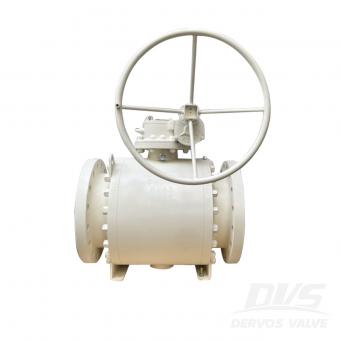
Refineries operate under some of the most demanding process conditions found in the energy industry. High pressure, elevated temperature, sour media, corrosive fluids, and frequent thermal cycling place strict requirements on valve performance. In these environments, ball valves are widely used because they provide reliable shutoff, low pressure loss, and fast operation. However, selecting the best ball valve for refinery applications depends less on the valve type itself and more on matching the design to the process conditions. Why Ball Valves Are Common in Refinery Service Refinery units handle hydrocarbons, hydrogen, steam, sulfur compounds, and various aggressive chemicals. If bubble-tight isolation is required, then trunnion mounted ball valves are generally preferred for larger sizes and higher pressure classes because seat loading remains stable under differential pressure. Floating ball valves are more common in small-bore lines where compact dimensions and simple construction are advantageous. API 6D and ASME B16.34 designs are frequently specified for refinery piping systems. Fire-safe construction in accordance with API 607 or API 6FA is often mandatory because accidental loss of soft seats must not result in external leakage. If the process medium contains hydrogen sulfide, then materials must comply with NACE MR0175 to reduce the risk of sulfide stress cracking. Material Selection Depends on Process Media Material compatibility is one of the primary factors affecting service life. Carbon steel valves are suitable for many hydrocarbon services, while stainless steel provides improved corrosion resistance in wet and chemically aggressive environments. Duplex and super duplex stainless steels are selected when chloride-induced corrosion becomes a concern. If the process contains sulfur compounds or sour gas, then hardness control and material qualification become critical. In high-temperature applications, thermal expansion must be considered because excessive growth can increase operating torque and accelerate seat wear. If severe erosion is expected, then hard-faced balls and seats with tungsten carbide or chromium carbide coatings can significantly improve durability. Sealing Performance and Failure Prevention Soft-seated ball valves provide excellent shutoff performance, but seat materials determine their temperature limits. PTFE and reinforced PTFE are common in moderate-temperature services, while PEEK offers improved mechanical strength and higher temperature capability. If temperatures exceed the limits of polymer seats, then metal-seated ball valves become a more suitable solution. Most valve failures in refineries are related to seat damage, stem leakage, or corrosion. If particulate contamination is present, then cavity fillers or metal seats may reduce wear. Double block and bleed configurations are often used where positive isolation is required for maintenance...
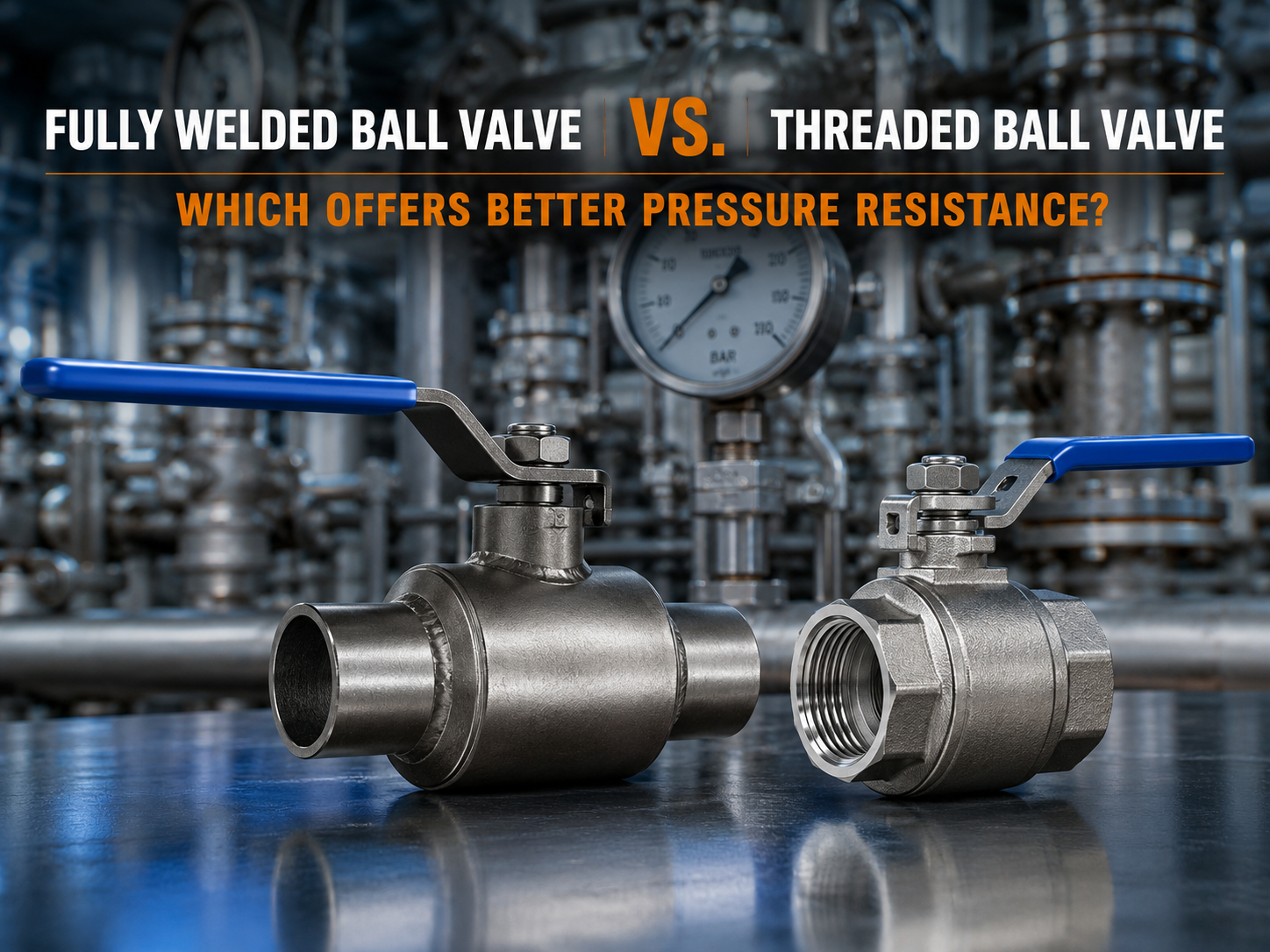
In natural gas transmission, district heating networks, petrochemical facilities, and industrial utility systems, ball valves are widely used for reliable flow isolation. One of the most common questions during valve selection is: Which provides better pressure resistance—a fully welded ball valve or a threaded ball valve? Understanding the Structural Difference Between Fully Welded and Threaded Ball Valves From a structural perspective, fully welded ball valves generally offer higher pressure-bearing capability. The valve body is manufactured using a fully welded construction, eliminating threaded body connections and reducing stress concentration points associated with mechanical joints. Under high-pressure conditions, frequent pressure fluctuations, or significant temperature changes, the welded structure can provide greater mechanical integrity and more stable sealing performance. Threaded ball valves, by contrast, rely on threaded connections to assemble the valve body. While this design simplifies installation and maintenance, threaded joints are inherently more susceptible to stress and deformation. As system pressure increases or when vibration and thermal expansion-contraction cycles are present, threaded connections may become vulnerable to loosening, potentially resulting in external leakage. Common field indications include leakage around the stem packing area, seepage from body connections, or accelerated wear of sealing components. Why Fully Welded Ball Valves Typically Offer Higher Pressure Resistance The primary advantage of a fully welded ball valve lies in its one-piece welded body construction. Without threaded body joints, the valve can better withstand internal pressure loads and reduce the possibility of leakage caused by connection failure. In applications involving high operating pressures, pressure surges, or repeated thermal cycles, the welded structure maintains better dimensional stability and structural strength. This is one of the key reasons why fully welded ball valves are widely used in gas transmission pipelines, district heating systems, and other critical infrastructure projects. How Sealing Performance Affects Pressure Capability In high-pressure service, valve failure is not determined solely by body strength. The sealing system also plays a critical role. Fully welded ball valves typically utilize an integral body design that minimizes potential external leakage paths and provides more consistent support for the seat sealing surfaces. In threaded ball valves, small dimensional changes at threaded joints during long-term pressure cycling may affect seat loading, potentially increasing the risk of internal leakage. If significant leakage, abnormal deformation, or pressure test failure is observed, the valve should be removed from service and inspected immediately. For flammable, toxic, or high-temperature media, disassembly and maintenance under pre...

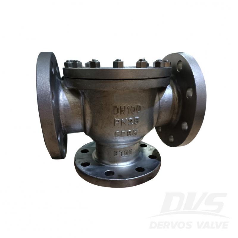
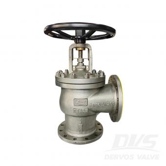
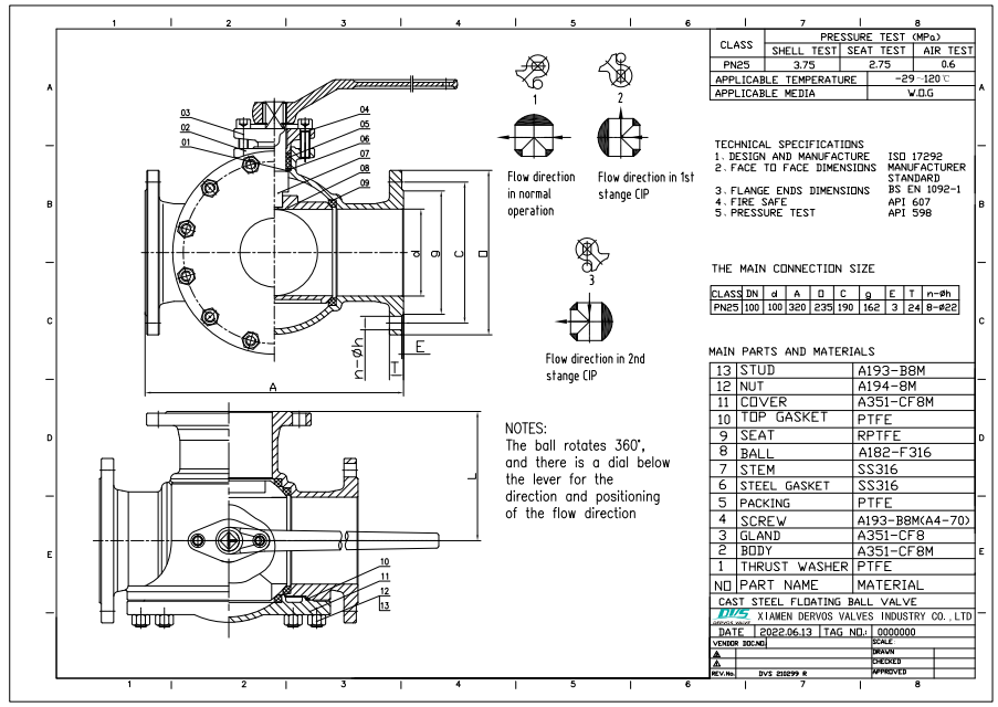
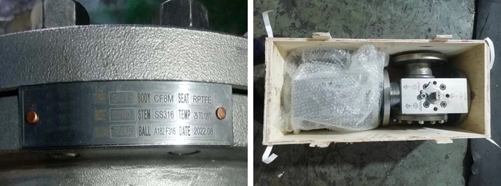
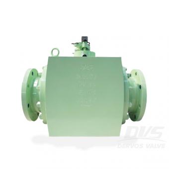
DN100 PN25 ball valve is made according to ISO 17292 standard. The valve body is made of A351-CF8M. It has the structural characteristics of T-shaped, floating ball, anti-fire, anti-static, anti-flying valve stem, bi-directional. Its connection mode is RF. And it has lever with dial operation mode.
Payment:
30% when order confirmed, 70% before shipmentProduct Origin:
ChinaColor:
CustomizationShipping Port:
Shanghai, ChinaLead Time:
30~60 days Ex Works after order confirmationMaterial:
A351-CF8MMethod of Operation:
Lever with dialProduct Description
|
Type |
Ball Valve |
|
Size |
DN100 |
|
Pressure |
PN25 |
|
Connection |
RF |
|
Operation |
Lever with dial |
|
Body Material |
A351-CF8M |
|
Design Norm |
ISO 17292 |
|
Face to Face Dimensions |
Manufacturer's Standard |
|
Flange Ends Dimensions |
BS EN 1092-1 |
|
Fire Safe |
API 607 |
|
Test & Inspection Code |
API 598 |
|
Temperature |
-29 ~ 120°C |
|
Applicable Medium |
Water, Oil and Gas |
Features
1. Low fluid resistance, simple structure, small volume, and light weight;
2. Tight and reliable, with good sealing, convenient operation and maintenance.
Technical Drawing
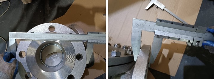
Dimension Checking
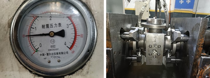
Pressure Testing
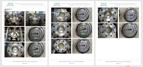
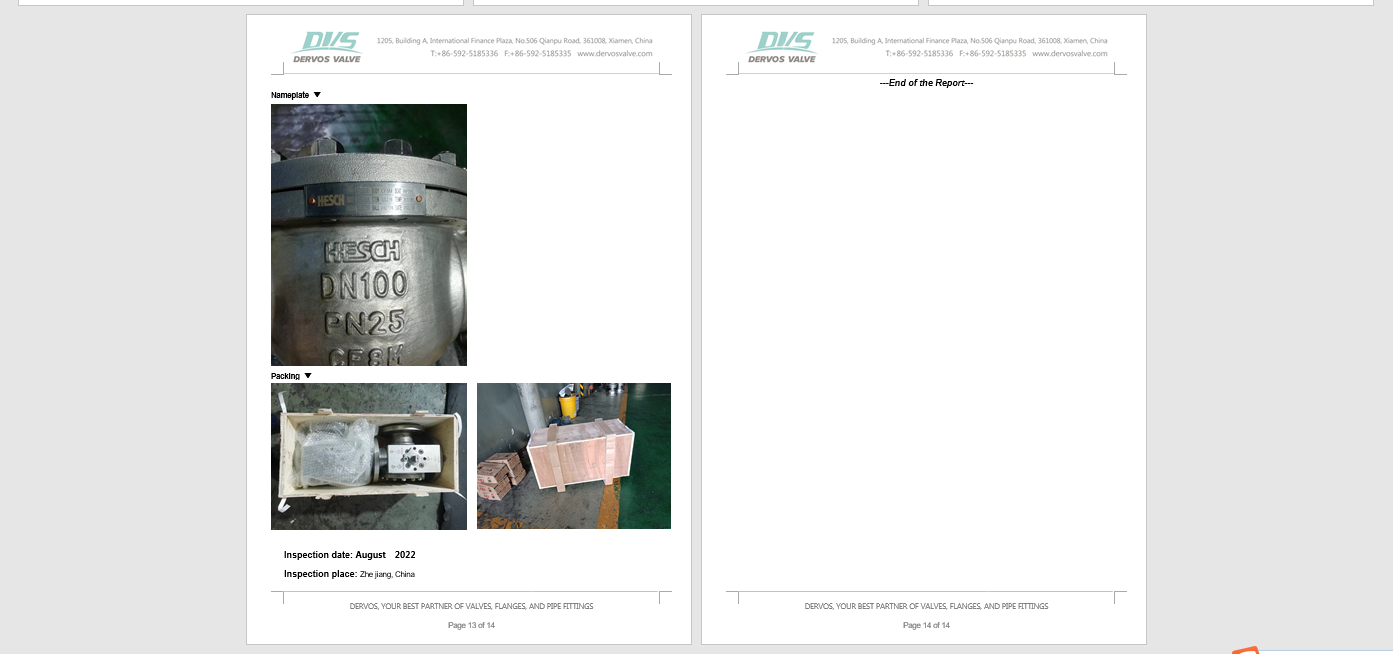
Nameplate & Packing
Inspection report
If you are interested in our products and want to know more details,please leave a message here,we will reply you as soon as we can.
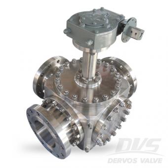
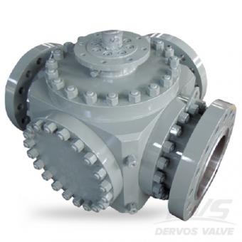
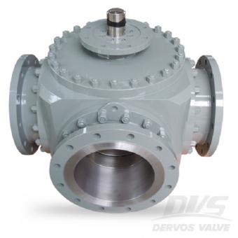
The 3 way T type ball valve owns flange connection, gearbox, ss304 body, ball and stem. The 3 inch flanged ball valve features in its T type three way ports which could connect any pair of ports or three ports together. Quick Detail Type Ball Valve Size 3" Pressure ANSI 300 Construction Three Way Ball Valve Connection Flanged Connection Operation Mode Gearbox Body Material A182 F304 Manufacture and Design API 6D Pressure & Temp ASME B16.34 End to End Code ASME B16.10 End Connection ASME B16.5 Inspection API 6D, API 598 Temperature Range -29℃~+200℃ Medium WOG Related Knowledge What is the difference between T port and L port 3-way ball valve? Normally speaking, 3-way ball valve can be divided into T type and L type. A T port three-way ball valve can connect any two ports, and even connect all three ports together at the same time. However, an L port three-way ball valve can only connect the center port with either side port or disconnect three ports. FAQ 1. Can the orders always be delivered on time? Our purchasing team follows up very closely with each order to make sure on-time delivery for most of orders. In 2018, more than 90% orders were delivered on time, and we are dedicated to doing better. 2. What’s the normal delivery lead time? For normal material, usually the delivery time is about 35~40 days, and for forged material, the delivery can even be shortened to 20~25 days. We believe the short lead time can make our offer more competitive and help you secure more orders. 3.Do you have different price levels for us? With our numerous suppliers, different price levels are available with us, so we are able to help you win more customer from different markets requesting for high, medium and low prices.
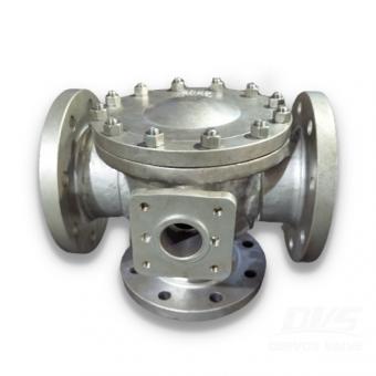
The DN100 3 way ball valve is isolating valve designed to redirect the service fluid flow rather than throttling or regulating purposes. Suitable for water, steam, gas, oil, crude oil, acid, alkali and other liquids and gases without mechanical impurities.
A three-way ball valve has three ports or openings that are connected to piping or tubing for gas or fluid flow (media) to pass through.
Copyright © 2015-2026 DERVOS VALVE CO.,LTD.All Rights Reserved Blog / Sitemap / XML / Privacy Policy