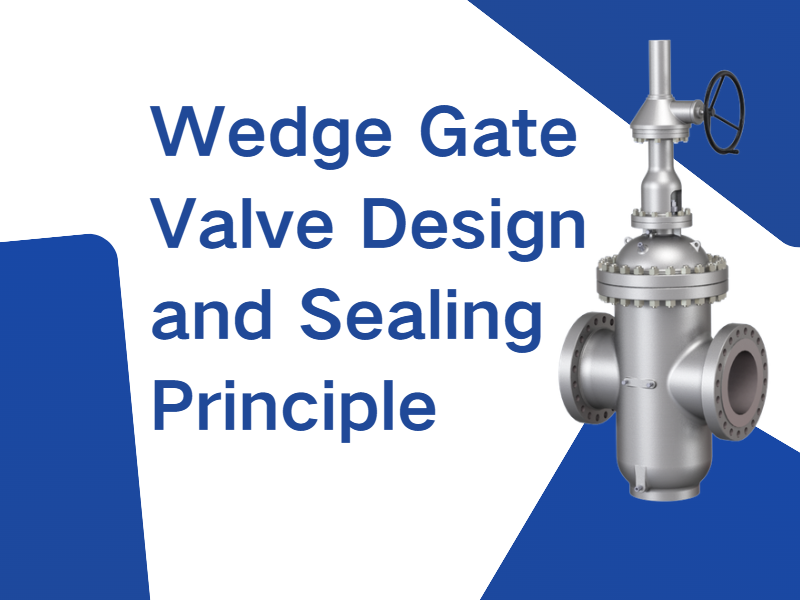
In a wedge gate valve, the gate sealing surfaces are wedge-shaped, forming a specific angle relative to the gate centerline. The gate is driven downward by the valve stem to achieve closure. As the stem thrust increases, the normal force acting on the wedge-shaped sealing surfaces also increases, creating a forced sealing effect. This design significantly improves sealing performance under low-pressure conditions. During opening, the gate sealing surfaces disengage from the seat immediately, which helps reduce wear on the sealing faces and extends the service life of the valve. Applicable Standards for Wedge Gate Valves Wedge gate valves are commonly manufactured in accordance with the following standards: ● GB/T 12234-2019 – Steel gate valves with bolted bonnet for petroleum and natural gas industries ● GB/T 12232-2005 – General-purpose flanged cast iron gate valves ● API Standard 600 (2015) – Steel gate valves for petroleum and natural gas industries Types of Wedge Gate Valve Gates Wedge gate valves are typically available in three gate configurations:Solid wedge gate, Flexible wedge gate, Double wedge gate. The flexible wedge gate and double wedge gate rely on controlled deformation of the sealing surfaces to achieve improved contact with the valve seat. This design enhances sealing reliability and effectively prevents gate binding or jamming caused by temperature variations, ensuring smooth operation even under fluctuating thermal conditions. Parallel Slide Gate Valve Design and Sealing Principle In a parallel slide gate valve, the sealing surfaces at both the inlet and outlet ends of the gate are parallel to the gate centerline. For single-gate configurations, sealing is primarily achieved by the medium pushing a floating gate or floating seat into position. In double-gate configurations, sealing can be accomplished through springs or an expansion mechanism between the gates. Throughout the opening and closing process, the gate and seat sealing surfaces remain in constant contact, ensuring reliable sealing. Applicable Standards for Parallel Slide Gate Valves Common standards for parallel slide gate valves include: ● GB/T 23300-2009 – Parallel slide gate valves ● JB/T 5298-2016 – Steel parallel slide gate valves for pipelines ● API 6D – Pipeline valves for petroleum and natural gas industries Types and Features of Parallel Slide Gate Valves Parallel slide gate valves are available in single-gate and double-gate configurations. ● Gates may include flow-through holes or be solid. Gates with flow-through holes match the seat inner diameter, facilitating cleaning and drainage of the pipeline. ● Sealing can be configured at the inlet end, outlet end, or at both ends, depending on application requirements. This design ensures flexibility in sealing arrangements while maintaining reliable oper...
Damage to valve sealing surfaces is typically the result of multiple contributing factors, including material selection, operating conditions, operating practices, and maintenance. The following is a categorized summary of the most common causes: 1. Mechanical Damage ● Wear: Solid particles in the medium (such as sand or welding slag) erode the sealing surface, resulting in scratches or grooves. ● Abrasive scuffing: Frictional wear caused by relative movement of the sealing surfaces during valve opening and closing, particularly in metal-to-metal sealing pairs. ● Impact damage: Deformation of the sealing surface caused by high-velocity fluid impingement or rapid valve opening and closing, leading to impact loading. 2. Chemical Corrosion ● Media corrosion: Acidic, alkaline, or oxidizing media directly attack the sealing surface material, such as metal corrosion caused by H₂S or chloride ions. ● Electrochemical corrosion: When sealing pairs made of dissimilar metals are exposed to an electrolyte, galvanic corrosion may occur due to electrochemical cell formation. ● Erosion–corrosion: The combined effect of corrosive media and high-velocity flow accelerates material loss on the sealing surface. 3. Thermal Damage ●Thermal fatigue:Frequent temperature fluctuations cause repeated thermal expansion and contraction of the sealing surface, leading to cracking or deformation. ●High-temperature oxidation:At elevated temperatures, the sealing surface may undergo oxidation, hardening, or burn-off, as commonly observed in steam valve applications. ●Thermal shock:Sudden exposure to high- or low-temperature media can cause cracking of the sealing surface, such as during rapid condensation or cold media ingress. 4. Improper Installation and Operation ●Installation misalignment: Incorrect valve installation or excessive piping stress can result in uneven loading on the sealing surfaces. ●Over-tightening: Excessive preload applied to the valve stem or bolting may crush or deform the sealing surface, particularly in soft-seated valves or soft sealing gaskets. ●Rough operation: Rapid opening and closing or excessive operating force can cause impact damage to the sealing surfaces. 5. Material Defects ●Improper material selection: The sealing surface material lacks sufficient resistance to process media, high temperature, or wear, such as the use of carbon steel in acidic service. ●Manufacturing defects: Defects in the hardfacing or overlay layer, including porosity, slag inclusions, or improper heat treatment, reduce wear resistance and overall sealing performance. 6. Abnormal Operating Conditions ●Cavitation / flashing: Pressure fluctuations in the fluid generate vapor bubbles that collapse and impact the sealing surface, a phenomenon commonly observed in valves installed downstream of pumps. ●Scaling / deposition: Impurities in the medium accumulate on the sealing surface, impairing tight shutoff, suc...
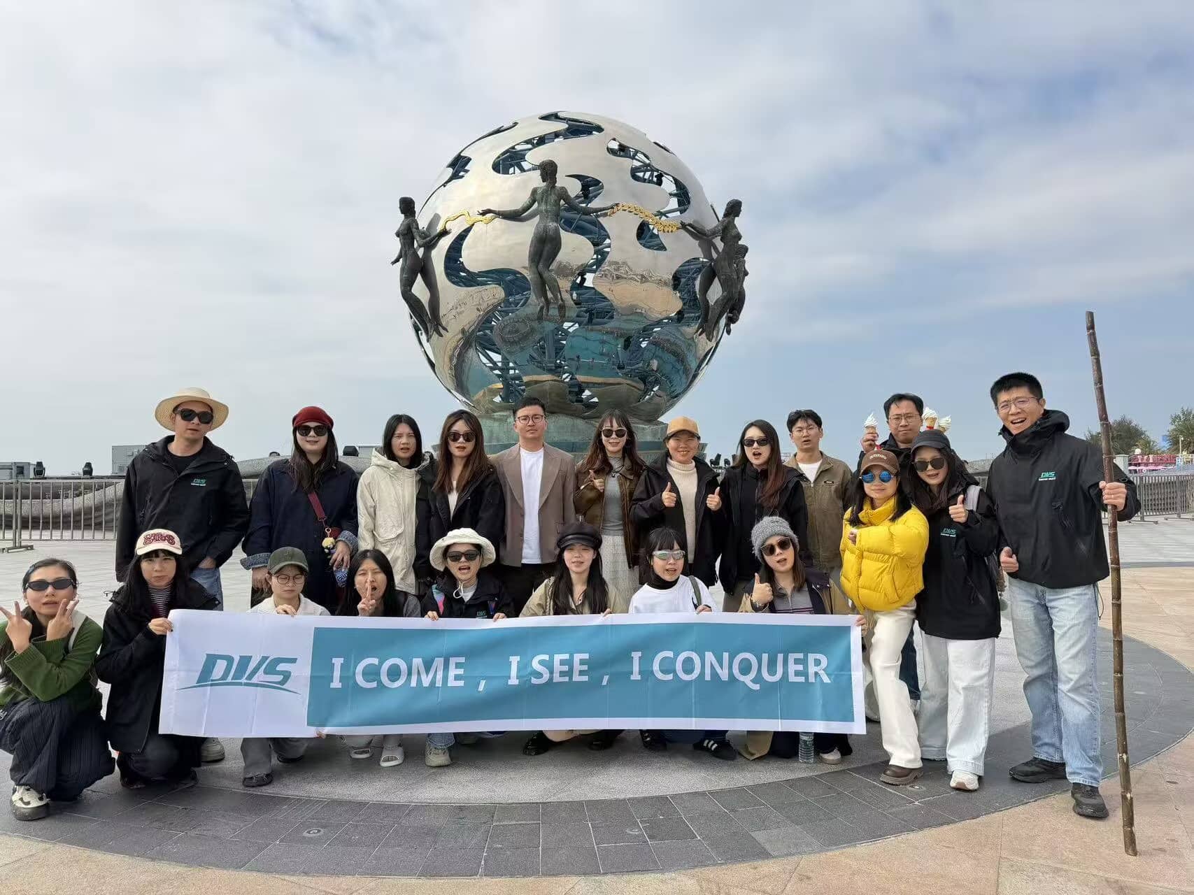
In 2025, Dervos organized its annual team trip, a five-day journey to Chongzuo, Weizhou Island, and Nanning in Guangxi Province. The trip aimed to provide relaxation and strengthen team communication, offering a well-paced and content-rich experience that combined natural landscapes with local cultural immersion. In Chongzuo, the team focused on nature sightseeing. Bamboo rafting tours allowed close observation of the local ecology and offered opportunities to see rare species such as the white-headed leaf monkey. The group also visited Detian Waterfall, experiencing its scale and flow firsthand. The overall itinerary was designed with a relaxed pace, providing ample time for rest and team bonding. Next, the team traveled to Weizhou Island. The volcanic landforms and coastal scenery added a unique visual dimension to the journey. Beyond sightseeing, participants engaged in local agricultural activities, including dragon fruit picking and banana harvesting, gaining insight into local lifestyles. The team also visited several beaches, fully appreciating the island environment. The final stop was Nanning. Team members explored the night market, sampled local specialties, and experienced the city’s daily life, bringing the Guangxi trip to a relaxed conclusion. This annual trip allowed the Dervos team to foster more natural communication and connection outside of work, recharging energy for the months ahead. Dervos remains committed to its guiding principle: I come, I see, I conquer!

Line blinds are utilized in pipeline systems when there is a need for either complete closure or unimpeded flow transition without a significant drop in pressure. The THD (Through-Hole Design) enables swift and seamless adjustments in position. The THD-slide variant boasts a multi-bolt configuration, making it easier to operate with reduced face-to-face dimensions. The inclusion of extra body bolts renders this style particularly well-suited for high-pressure applications.
Payment:
30% when order confirmed, 70% before shipmentProduct Origin:
ChinaColor:
CustomizationShipping Port:
Shanghai, ChinaLead Time:
30~60 days Ex Works after order confirmationFeatures
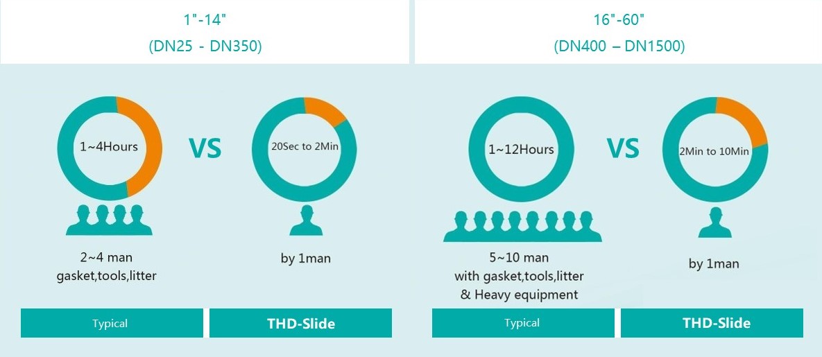
1. Swift Transition: Blinding can be performed safely in a matter of minutes, even by operators with minimal experience.
2. Economical Solution: Decreases maintenance hours, resulting in savings on labor costs.
3. Toolless Handling: The process is simplified with a hand-wheel operation, eliminating the need for tools to achieve full shut-off.
Standard Specifications
|
Size |
1'' - 60'' (DN 25 to DN 1500) |
|
Pressure Class |
Class 150 - 2500 (PN 2.5 to PN 400) |
|
Design & Manufacture code |
ASME B16.34 |
|
Flange Standard |
ASME B16.5 |
|
Material |
Carbon Steel, Stainless Steel, Hastelloy, and Titanium |
|
Actuation |
Manual, Pneumatic Hydraulic and Electric |
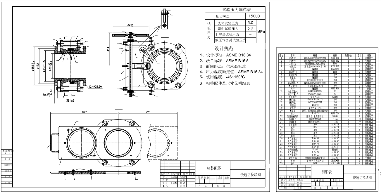
Technical Drawing
Adaptable Design
In addition to its conventional design, the THD-Slide is available in variations tailored for High-Temperature, Fire Safety, and Non-Drip applications. For installations constrained by limited space, a compact version can be provided as well.
Easy Seal Inspection
In this design, the seals are housed within the spectacle plate. This characteristic offers the advantage of convenient access for inspection and seal replacement. Assessing the condition of these seals can be performed external to the operational process, prior to any position changes, thereby ensuring the integrity of the seal's quality.
Cost Effectiveness
The THD-Slide features a straightforward and robust design engineered to deliver complete shutdown, extended operational lifespan, and cost-effective service with minimal maintenance requirements. The distinctive mechanism for opening and closing the THD-Slide enables a single individual to rapidly and safely blind pipelines without the need for any tools or equipment.
THD-Slide Cutout
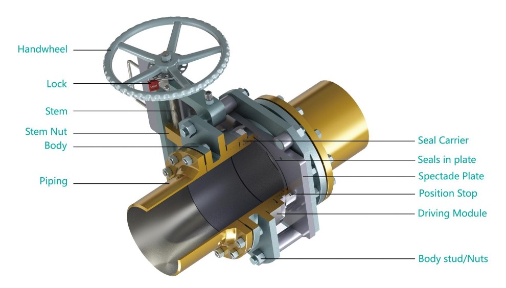
Part Description
|
Part Description |
Material |
|
Handwheel |
QT400-18 |
|
Stem |
A182 F6A |
|
Stem Nut |
Alloy Copper |
|
Body |
A350 LF2 |
|
Seal Carrier |
A350 LF2 |
|
Seals in plate |
Viton |
|
Spectade Plate |
A350 LF2+ENP |
|
Position Stop |
A193 B7 |
|
Driving module |
A350 LF2 |
|
Body stud/Nuts |
A193 B7/A194 2H |
|
Other materials and seal rings are available upon request |
|
Options
●Hand Wheel Extensions
●Locking Device
●Limit Switches
●Drain/Vent ports
●Spectacle Plate Covers to Protect Seals
●Compact Design (integral tapped end flange)
●Rain/Dust Shield
●Torque Limiter
Operation of Standard
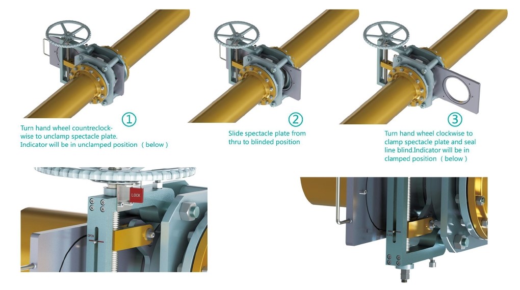
Mechanism Principle
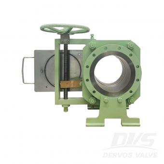
In normal conditions, the blind valve's diversion hole is in contact with the pipeline, and the blind valve is in the open position. When maintenance is required, and the pipeline must be cut off, then loosen the stem of blind valve to move the flat end onto the pipeline, and make the blind valve turn to closed position from open position; tighten the stem and let the blind valve to perform sealing function and cut off the pipeline.
When the maintenance work is completed, loosen the stem and move the blind plate to the diversion hole and connected to the pipeline. The blind valve was turned to closed position from open one. Lock the stem, and seal it, the pipeline is now open, and the blind plate valve returns to the open position.
If you are interested in our products and want to know more details,please leave a message here,we will reply you as soon as we can.
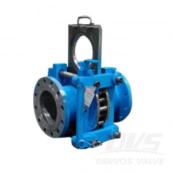
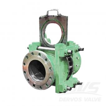
Line blind valve (eyeglass valve) is a kind of gate valve that cuts off gas medium manually, electrically or pneumatically or hydraulically. It is generally divided into electric blind valve, hydraulic blind valve, closed plug valve and electric open blind valve.
Line blind valve is a kind of gate valve that cuts off gas medium manually, electrically or pneumatically or hydraulically. It is generally divided into electric blind valve, hydraulic blind valve, closed plug valve and electric open blind valve.
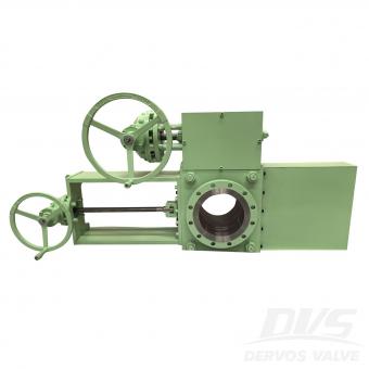
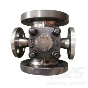
10" 150LB line blind valve is made according to ASME B16.34 standard. The valve body is made of A105. It has the structural characteristics of anti-drip. Its connection mode is RF. And it has turbine operation mode.
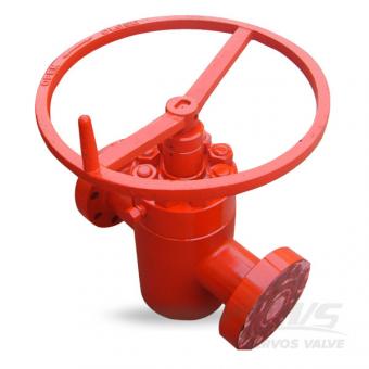
Made of carbon steel, the 4 1/16" wellhead gate valve is designed per API 6A with RTJ flange, non rising stem, parallel gate as its features. Design Feature 1.Full port design for small flow resistance 2.Small torque value for easy operation 3.No limitation for flow direction 4.Parellel disc 5.Self-tightening seal packing minimizes maintenance 6.Metal to metal seat for stem and wedge 7.Compact structure with light weight Quick Detail Type Wellhead Gate Valve Size 4.1/16" Nominal Pressure 10000PSI Construction Parallel Gate, Non-Rising Stem Connection Flange Operation Handwheel Operation Body Material ANSI 4130 Trim Matetial SS410 Material Class EE TempretureClass P-U ProductSpecificationLevel PSL3 PerformanceRequirement PR2 Medium Water, Oil and Gas Origin China Product Application Dervos valves can be widely used in varieties of industries, such as petrochemical, pipeline, oil & gas, marine, water treatment, power station industries and etc.
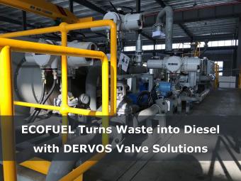
In 2017, DERVOS contributed to an innovative environmental initiative led by ECOFUEL, an emerging canadian player in clean technology. This groundbreaking project aimed to produce sustainable diesel from solid waste, setting a precedent in green energy solutions. DERVOS is proud to have provided 136 sets of premium valves to support this pioneering effort.
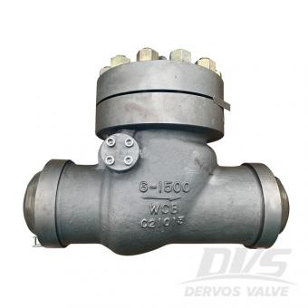
6" 1500LB swing check valve is made according to API 6D standard. The valve body is made of WCB. It has the structural characteristics of swing type. It has BW connection mode.
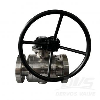
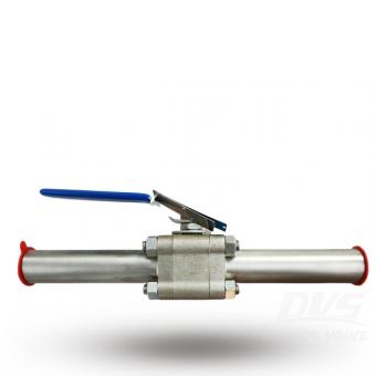
3" 600LB ball valve is made according to API6D standard. The valve body is made of A182 F304. It has the structural characteristics of fixed ball, full bore, anti-fire and anti-static and anti-flying valve stem. Its connection mode is RF. And it has IP68 waterproof turbine box operation mode.
The 3 inch 150LB expanding plug valves are designed for applications in which positive shutoff, verifiable zero leakage, and double block-and-bleed capabilities are required.
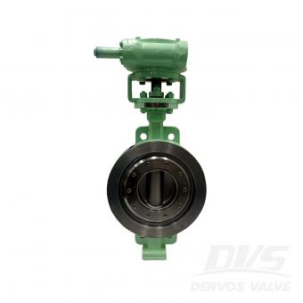
DN250 PN10 butterfly valve is made according to EN593 standard. The valve body is made of ASTM A216 WCB. It has the structural characteristics of three eccentricities, bidirectional one to one pressure test. Its connection mode is wafer. And it has turbine operation mode.
1" 150LB swing check valve is made according to API 602 standard. The valve body is made of A105. It has the structural characteristics of bolt cover, swing type and full bore. Its connection mode is RF (Welded Flange).
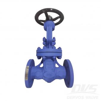
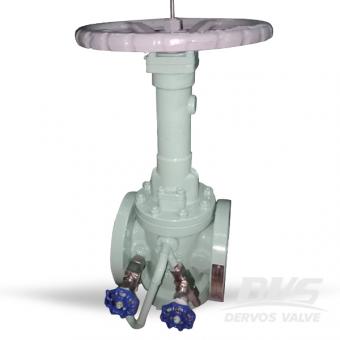
DN50 PN16 Cast Steel gate valve is made according to BS EN 1984 standard. The valve body is made of ASTM A216 WCB. It has the structural characteristics of bolt cover, exposed pole. Its connection mode is EN1092-1 B. And it has Hand Wheel operation mode.
Dervos manufactures a versatile range of Ball Valves in single, two and three piece constructions. The valves are available in full-bore and regular-bore designs, in a variety of end connections and materials to meet your requirements.
Copyright © 2015-2026 DERVOS VALVE CO.,LTD.All Rights Reserved Blog / Sitemap / XML / Privacy Policy