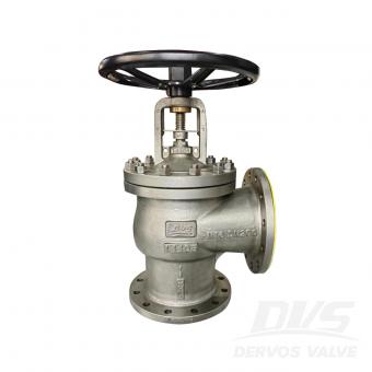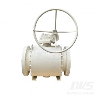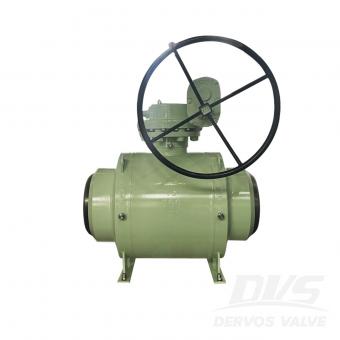
1. Suzhou Neway Valve Co., Ltd. — NEWAY NEWAY is one of China's most internationally recognized industrial valve manufacturers. Its product range includes ball valves, gate valves, globe valves, check valves, butterfly valves, cryogenic valves, subsea valves, and other engineered valve solutions. The company has strong experience in oil and gas, LNG, petrochemical, offshore, and power applications. Best suited for: large-scale energy projects and severe-service applications. 2. CNNC Sufa Technology Industry Co., Ltd. CNNC SUFA is well known for its experience in nuclear power and other high-integrity industrial applications. The company has strong capabilities in material traceability, engineering control, testing, and specialized valve manufacturing. Its products are also used in petroleum, petrochemical, power, and chemical industries. Best suited for: nuclear power, high-integrity systems, and technically demanding projects. 3. DERVOS VALVE DERVOS VALVE supplies industrial valves to customers in oil and gas, petrochemical, power generation, water treatment, marine, and general industrial applications. Its main products include ball valves, gate valves, globe valves, check valves, butterfly valves, plug valves, knife gate valves, line blind valves, and strainers. DERVOS supports international standards such as API, ASME, EN, and DIN, and can provide carbon steel, stainless steel, alloy steel, duplex stainless steel, low-temperature steel, and other materials. One of its key strengths is flexibility. DERVOS can support mixed valve packages, small-to-medium quantities, customized specifications, and project-specific documentation. Best suited for: overseas distributors, EPC projects, customized valves, mixed orders, and flexible sourcing requirements. 4. Yuanda Valve Group Yuanda Valve Group is one of China's large-scale valve manufacturers with broad production capacity. Its product range includes gate valves, globe valves, check valves, butterfly valves, ball valves, and other general industrial valves. The company is widely involved in water supply, HVAC, municipal infrastructure, power, and industrial pipeline projects. Best suited for: large-volume standardized valve procurement and general industrial applications. 5. Jiangsu Shentong Valve Co., Ltd. Jiangsu Shentong focuses strongly on specialized valve applications in metallurgy, energy, nuclear power, and chemical industries. Its strength lies in engineered products for demanding operating conditions rather than only standard valve production. Best suited for: metallurgy, energy, chemical processing, and specialized industrial applications. 6. Chaoda Valves Group Co., Ltd. Chaoda Valves Group serves petroleum, chemical, natural gas, power, and other process industries. Its product range includes ball valves, gate valves, globe valves, check valves, butterfly valves, and special-purpose industrial valves. The company has experience with corro...
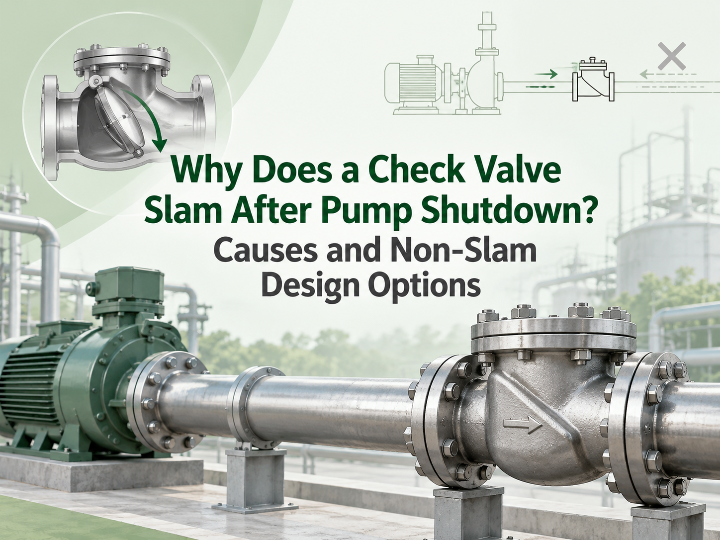
A check valve slams after pump shutdown when flow reverses before the closure member reaches its seat. The valve then stops that reverse velocity abruptly, creating a pressure wave through the piping. The damaging event is usually the rapid arrest of the liquid column, not simply the disc hitting the seat. A “non-slam” label alone is not a solution; the valve response must suit the system's flow deceleration. The Valve Is Closing Too Late for the Shutdown Transient When pump torque disappears, forward velocity falls. Static head, a pressurised common header or another running pump may then drive liquid back toward the stopped pump. If inertia and hinge friction keep a conventional swing disc open through zero flow, reverse velocity develops before the disc reaches its seat. High static lift, a steep rising main, short pump coast-down, parallel pumps and high initial velocity can accelerate this reversal. A long-stroke or high-inertia valve is more likely to lag. This is why the same valve may run quietly in one system and slam in another: nominal size and pressure class do not define shutdown behaviour. Confirm the Event Before Changing the Valve A single hard bang after shutdown points toward check-valve closure or another surge event. Continuous clicking during forward flow is chatter, which more often indicates unstable partial opening, pulsation or poor hydraulic sizing. Record the stop command, motor speed decay, flow direction and pressures on both sides of the valve on a common time base. A high-speed video of an external lever or position indicator can help show when the valve closes. For consequential systems, fast pressure logging is more reliable than sound alone. Inspect the hinge, shaft, spring and seat for friction, wear, deposits or damage, and verify the permitted installation orientation. Check pipe supports as well; the pressure wave may produce its loudest noise away from the valve. Non-Slam Designs Use Different Closing Strategies An axial-flow or nozzle check valve uses a light, centrally guided disc, short travel and spring assistance. It begins closing as forward flow falls, ideally seating before appreciable reversal. It is a strong candidate for rapid pump trips, but pressure loss, cracking pressure, minimum stable flow, orientation and tolerance of solids still matter. A spring-assisted dual-plate valve uses two lighter plates and shorter travel than a conventional swing disc. Its compact construction can improve response, but “dual plate” does not mean slam-free. Plate inertia, spring torque, size and mounting position remain relevant. Tilting-disc, resilient-hinge and spring-assisted swing designs reduce travel or assist closure while retaining a relatively open flow path. They can suit large water lines where energy loss matters, provided dynamic data supports the selected design and size. Large pumping mains ma...
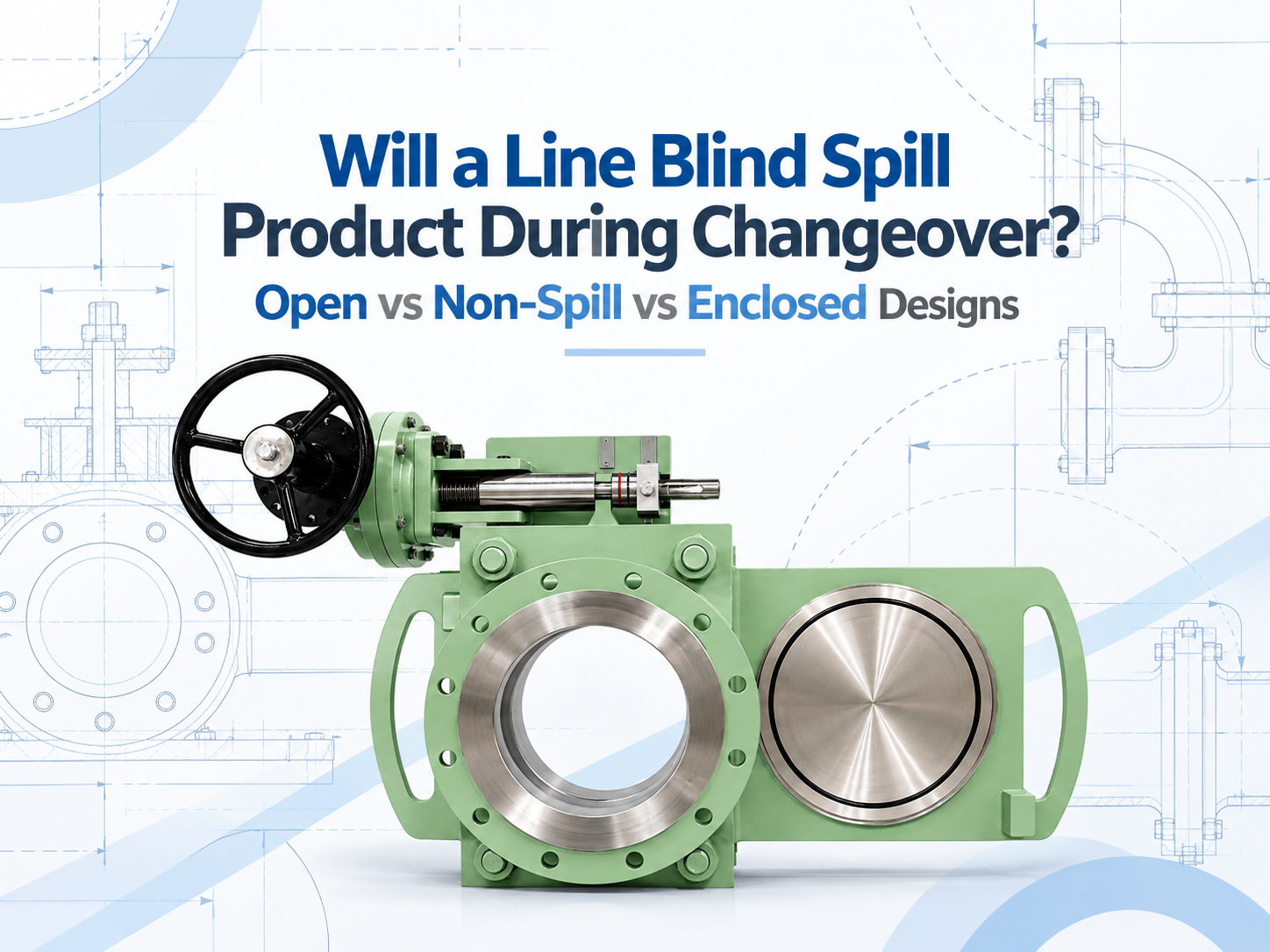
Yes, an open-body line blind can release residual product when it changes between the open and blind positions. A non-spill design does not make that residue disappear; it catches the liquid in a partial enclosure and directs it to a drain. An enclosed design can provide better control of liquid and vapour, but only when its housing, drain, vent and purge connections are engineered for the service. None of these labels should be read as permission to move the blind under live line pressure. Why Product Can Escape During Changeover When a line blind is fully clamped, its seals contain the process and the solid plate provides positive isolation in the blind position. Changeover is different. The sealing faces must separate before the spectacle or sliding plate can move. During that interval, the body cavity and plate path may be open to the surrounding area. The line should already be isolated, depressurised and drained, but “drained” rarely means perfectly dry. Liquid can remain as a film on the plate, collect in the lower body, or sit in a poorly drained pipe pocket. Gas service may leave flammable, toxic or odorous vapour. The amount released therefore depends as much on piping layout and the shutdown procedure as on the line blind itself. The Three Designs Manage Residue Differently Open-body design Residual liquid can drip from the exposed plate path into a temporary tray or the work area, while vapour disperses locally. This arrangement can suit water, steam condensate or other manageable media where easy access and visual inspection matter. It presents the highest potential for floor contamination and operator exposure. Non-spill design A bottom-and-side cover catches drips and sends them to a drain or recovery container; the top may remain open. This design is commonly considered for fuel terminals, marine service and liquid duties where ground or deck contamination must be controlled. It reduces dripping but may not contain vapour, and a blocked drain defeats its purpose. Enclosed design A housing surrounds more or all of the plate travel and may connect to a closed drain, purge, vent, flare or vapour-recovery system. It is better suited to toxic, flammable, odorous or environmentally sensitive service requiring controlled containment. The tradeoff is greater complexity in purging, inspection and maintenance, together with the need to manage trapped pressure deliberately. These names are not perfectly standardised across manufacturers. One supplier's “non-spill” model may be open at the top, while another product described as enclosed may use a more complete casing. The RFQ should show the enclosure arrangement and identify every opening rather than relying on the product name. Non-Spill Does Not Automatically Mean Zero Release For a liquid with low volatility, catching the remaining drops and routing them into a closed contai...
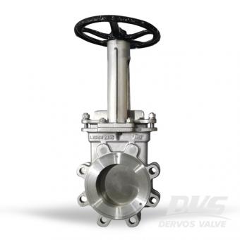
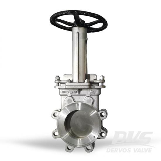
The knife gate is a bi-directional lug type valve designed according to MSS-SP-81 and for industrial service applications. The design of the body and seat assures non-clogging shut off on suspended solids in industries.
Payment:
30% when order confirmed, 70% before shipmentProduct Origin:
ChinaColor:
CustomizationShipping Port:
Shanghai, ChinaLead Time:
30~60 days Ex Works after order confirmationMaterial:
2205Method of Operation:
HandwheelQuick Detail
|
Type |
KnifeGate Valve |
|
Size |
6'' |
|
Design Pressure |
150LB |
|
Construction |
Knife Type Gate Valve |
|
Connection Type |
Lug Type, RF |
|
Operation Type |
Hand wheel |
|
Body Material |
2205 |
|
Seat Material |
EPDM |
|
Design Code |
MSS SP-81 |
|
Flange Dimensions |
ASME B16.5 |
|
Temp. Range: |
-29~.+120℃ |
|
Medium |
Water, Oil and Gas |
|
Origin |
China |
Features
All stainless steel design
Standard knife gate valves: NPS 2–24 (DN 50–600)
Bolted bonnet knife gate valves: NPS 4–24 (DN 50–600)
ASME Classes: 1690-4500
0-14ph packing standard
Locking device on standard knife gate valve
Environmentally friendly bi-directional bolted bonnet and standard body styles
Resilient and metal seats
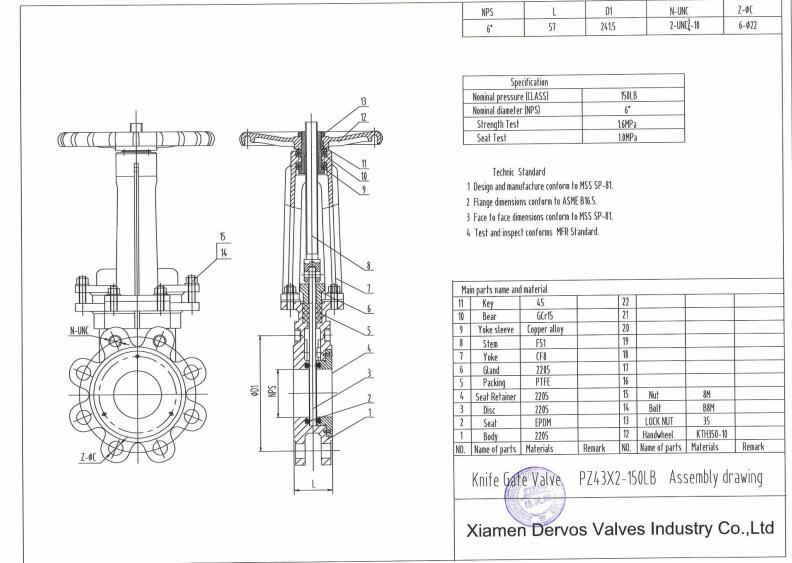
Technical Drawing
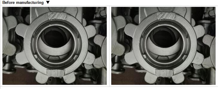
Before Manufacturing
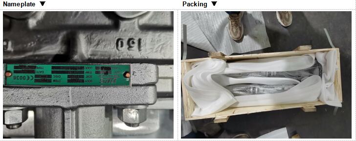
Nameplate&Packaging
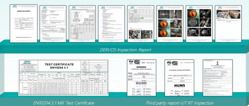
Reports
For each order, Dervos will provide inspection reports to show you the whole inspection process and results. Plus, we will provide material report to let you know that the material we provide is as per standards.
If you are interested in our products and want to know more details,please leave a message here,we will reply you as soon as we can.
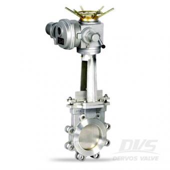
The 6 inch stainless steel gate valve, designed as per MSS-SP-81, has the lug type connection per Class 150 and electric actuator. Quick Detail Type Knife Gate Valve Size 6'' Design Pressure ANSI 150 Construction Knife Type Gate Valve ConnectionType Lug Type OperationType Electric Actuator Body Material ASTM A351 CF8 TrimMaterial SS304 Design Code MSS SP81 Medium Water, Oil and Gas Origin China Related Knowledge What are knife gate valves used for? Knife gate valves are originally designed for paper industry. The knife gate valve is especially applicable for heavy liquids with solid particulates, like slurry liquid, that are most corrosive, erosive and abrasive. Compared to wedge gate valve, the knife gate valve has a shorter end to end dimension and lighter weight. Plus, the knife valve has a more sharpened disc to cut through slurry and viscous medium. Both wedge gate valve and knife gate valve can only be used for on-off function not for regulating the flow. Dervos Customer Service With Dervos customer service, you will not have any concern before, during and after buying valves. Pre-sales We will reply on time and also provide technical support upon your request. Order We will check the production details with factory and customers. Sales confirmation will also be sent. During production, we will also send weekly report to let you know the order status. Before shipment, delivery note will be sent to let you know the situation. 18 Month warranty Dervos is always responsible for their products. We will provide 18 months warranty to let our customers without concern.
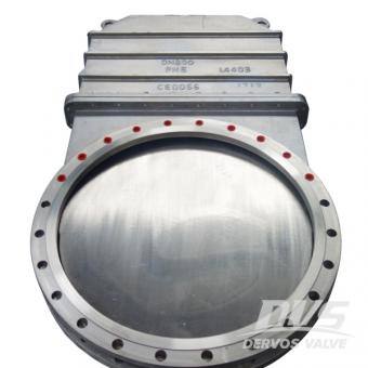
The stainless steel knife gate valve is designed with DN800 PN6 flange end and gearbox operation. The soft seated knife gate valve has a unidirectional sealing. Quick Detail Type Gate Valve Size DN800 Design Pressure PN6 Construction Unidirectional, Soft Seated ConnectionType Flange End OperationType Gearbox Operated Body Material CF8M DiscMaterial SS316L StemMaterial SS316 SeatMaterial PTFE Design Code MSS SP81 Medium Water, Oil and Gas Origin China Dimension Checking Pressure Tesing
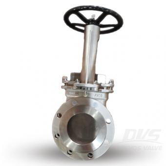
The DN150 PN10 unidirectional knife gate valve features a single piece, stainless steel body design provides tested performance in applications ranging from general purpose to severe media.
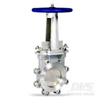
The lug type knife gate valve is designed per MSS-SP-81.Made by stainless steel CF8, the 4 inch gate valve has 150 LB flange connection and handwheel operation.
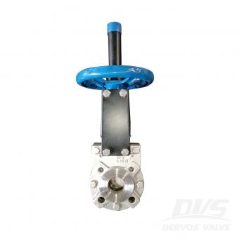
2" 150LB knife gate valve is made according to MFS standard. The valve body is made of ASTM A351 CF8. It has the structural characteristics of bilateral sealing and with flow deflector. Its connection mode is lug. And it has hand wheel operation mode.
Copyright © 2015-2026 DERVOS VALVE CO.,LTD.All Rights Reserved Blog / Sitemap / XML / Privacy Policy