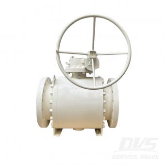
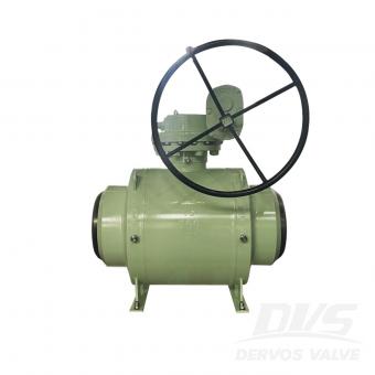
Refineries operate under some of the most demanding process conditions found in the energy industry. High pressure, elevated temperature, sour media, corrosive fluids, and frequent thermal cycling place strict requirements on valve performance. In these environments, ball valves are widely used because they provide reliable shutoff, low pressure loss, and fast operation. However, selecting the best ball valve for refinery applications depends less on the valve type itself and more on matching the design to the process conditions. Why Ball Valves Are Common in Refinery Service Refinery units handle hydrocarbons, hydrogen, steam, sulfur compounds, and various aggressive chemicals. If bubble-tight isolation is required, then trunnion mounted ball valves are generally preferred for larger sizes and higher pressure classes because seat loading remains stable under differential pressure. Floating ball valves are more common in small-bore lines where compact dimensions and simple construction are advantageous. API 6D and ASME B16.34 designs are frequently specified for refinery piping systems. Fire-safe construction in accordance with API 607 or API 6FA is often mandatory because accidental loss of soft seats must not result in external leakage. If the process medium contains hydrogen sulfide, then materials must comply with NACE MR0175 to reduce the risk of sulfide stress cracking. Material Selection Depends on Process Media Material compatibility is one of the primary factors affecting service life. Carbon steel valves are suitable for many hydrocarbon services, while stainless steel provides improved corrosion resistance in wet and chemically aggressive environments. Duplex and super duplex stainless steels are selected when chloride-induced corrosion becomes a concern. If the process contains sulfur compounds or sour gas, then hardness control and material qualification become critical. In high-temperature applications, thermal expansion must be considered because excessive growth can increase operating torque and accelerate seat wear. If severe erosion is expected, then hard-faced balls and seats with tungsten carbide or chromium carbide coatings can significantly improve durability. Sealing Performance and Failure Prevention Soft-seated ball valves provide excellent shutoff performance, but seat materials determine their temperature limits. PTFE and reinforced PTFE are common in moderate-temperature services, while PEEK offers improved mechanical strength and higher temperature capability. If temperatures exceed the limits of polymer seats, then metal-seated ball valves become a more suitable solution. Most valve failures in refineries are related to seat damage, stem leakage, or corrosion. If particulate contamination is present, then cavity fillers or metal seats may reduce wear. Double block and bleed configurations are often used where positive isolation is required for maintenance...
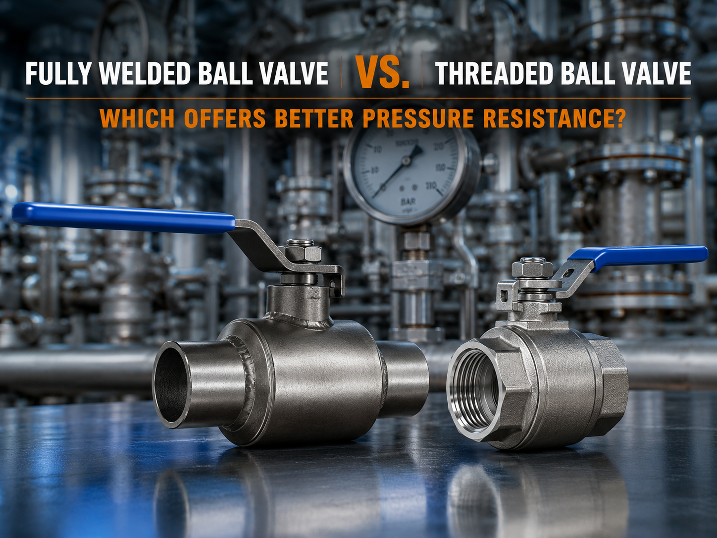
In natural gas transmission, district heating networks, petrochemical facilities, and industrial utility systems, ball valves are widely used for reliable flow isolation. One of the most common questions during valve selection is: Which provides better pressure resistance—a fully welded ball valve or a threaded ball valve? Understanding the Structural Difference Between Fully Welded and Threaded Ball Valves From a structural perspective, fully welded ball valves generally offer higher pressure-bearing capability. The valve body is manufactured using a fully welded construction, eliminating threaded body connections and reducing stress concentration points associated with mechanical joints. Under high-pressure conditions, frequent pressure fluctuations, or significant temperature changes, the welded structure can provide greater mechanical integrity and more stable sealing performance. Threaded ball valves, by contrast, rely on threaded connections to assemble the valve body. While this design simplifies installation and maintenance, threaded joints are inherently more susceptible to stress and deformation. As system pressure increases or when vibration and thermal expansion-contraction cycles are present, threaded connections may become vulnerable to loosening, potentially resulting in external leakage. Common field indications include leakage around the stem packing area, seepage from body connections, or accelerated wear of sealing components. Why Fully Welded Ball Valves Typically Offer Higher Pressure Resistance The primary advantage of a fully welded ball valve lies in its one-piece welded body construction. Without threaded body joints, the valve can better withstand internal pressure loads and reduce the possibility of leakage caused by connection failure. In applications involving high operating pressures, pressure surges, or repeated thermal cycles, the welded structure maintains better dimensional stability and structural strength. This is one of the key reasons why fully welded ball valves are widely used in gas transmission pipelines, district heating systems, and other critical infrastructure projects. How Sealing Performance Affects Pressure Capability In high-pressure service, valve failure is not determined solely by body strength. The sealing system also plays a critical role. Fully welded ball valves typically utilize an integral body design that minimizes potential external leakage paths and provides more consistent support for the seat sealing surfaces. In threaded ball valves, small dimensional changes at threaded joints during long-term pressure cycling may affect seat loading, potentially increasing the risk of internal leakage. If significant leakage, abnormal deformation, or pressure test failure is observed, the valve should be removed from service and inspected immediately. For flammable, toxic, or high-temperature media, disassembly and maintenance under pre...
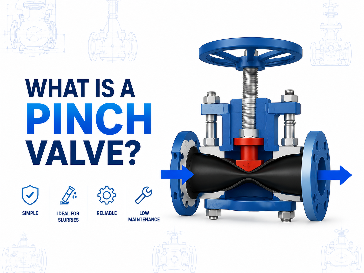
Introduction A pinch valve is a type of linear valve in which the flow of fluid is controlled by compressing a flexible sleeve. Unlike conventional metal-seated valves, pinch valves rely on a resilient elastomer tube that is “pinched” closed by a mechanical or pneumatic actuator to stop or regulate flow. This design allows full-bore flow with minimal obstruction when open and tight shut-off when closed, making pinch valves suitable for abrasive, corrosive, or slurry-type media. Pinch valves are used across industries such as water and wastewater treatment, chemical processing, mining, pneumatic conveying, and slurry handling. Their simple structure and minimal internal components make them resistant to clogging, easy to maintain, and particularly effective in systems where suspended solids or corrosive chemicals are present. Structure and Working Principle The key element of a pinch valve is its elastomer sleeve, which serves as both the sealing surface and the flow channel. When the actuator compresses the sleeve against the valve body, the valve closes and prevents fluid passage. Releasing the pinch pressure allows the sleeve to return to its original shape, enabling full flow. Valves may have manual, pneumatic, or electric actuators. The sleeve material—commonly natural rubber, EPDM, NBR, or specialty compounds—is selected based on chemical compatibility, temperature limits, and abrasion resistance. The valve body, typically made of carbon steel, stainless steel, or plastic, provides structural support and pressure containment. Key Advantages and Engineering Considerations Pinch valves are appreciated for their simplicity and reliability in handling challenging fluids. Because the sleeve is the only wetted component, there is minimal contact between the media and the valve body, reducing corrosion risk. They are inherently “full bore,” which minimizes pressure drop and makes them suitable for high-solids content flows. However, their performance depends heavily on proper sleeve selection, pinch force, and actuator alignment. Misapplication—such as exceeding temperature limits, using incompatible chemicals, or operating with high-pressure abrasive slurry—can accelerate sleeve wear, affect sealing integrity, or shorten service life. For engineers and procurement professionals, specifying the correct sleeve material, actuator type, and pressure rating is crucial to ensure reliable operation. Practical Advice for Industrial Use Maintenance is generally straightforward: sleeve inspection, replacement schedules, and actuator calibration are the main tasks. In critical systems handling toxic, flammable, or high-temperature media, maintenance must follow strict lockout-tagout and isolation procedures. Selecting a sleeve material with both chemical resistance and abrasion tolerance is key to extending service life, while actuator force ...

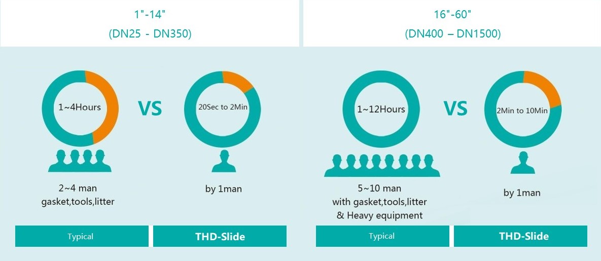
Line blinds are utilized in pipeline systems when there is a need for either complete closure or unimpeded flow transition without a significant drop in pressure. The THD (Through-Hole Design) enables swift and seamless adjustments in position. The THD-slide variant boasts a multi-bolt configuration, making it easier to operate with reduced face-to-face dimensions. The inclusion of extra body bolts renders this style particularly well-suited for high-pressure applications.
Payment:
30% when order confirmed, 70% before shipmentProduct Origin:
ChinaColor:
CustomizationShipping Port:
Shanghai, ChinaLead Time:
30~60 days Ex Works after order confirmationFeatures
1. Swift Transition: Blinding can be performed safely in a matter of minutes, even by operators with minimal experience.
2. Economical Solution: Decreases maintenance hours, resulting in savings on labor costs.
3. Toolless Handling: The process is simplified with a hand-wheel operation, eliminating the need for tools to achieve full shut-off.
Standard Specifications
|
Size |
1'' - 60'' (DN 25 to DN 1500) |
|
Pressure Class |
Class 150 - 2500 (PN 2.5 to PN 400) |
|
Design & Manufacture code |
ASME B16.34 |
|
Flange Standard |
ASME B16.5 |
|
Material |
Carbon Steel, Stainless Steel, Hastelloy, and Titanium |
|
Actuation |
Manual, Pneumatic Hydraulic and Electric |
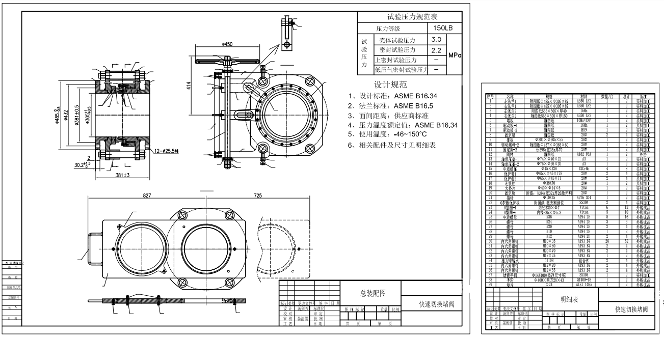
Technical Drawing
Adaptable Design
In addition to its conventional design, the THD-Slide is available in variations tailored for High-Temperature, Fire Safety, and Non-Drip applications. For installations constrained by limited space, a compact version can be provided as well.
Easy Seal Inspection
In this design, the seals are housed within the spectacle plate. This characteristic offers the advantage of convenient access for inspection and seal replacement. Assessing the condition of these seals can be performed external to the operational process, prior to any position changes, thereby ensuring the integrity of the seal's quality.
Cost Effectiveness
The THD-Slide features a straightforward and robust design engineered to deliver complete shutdown, extended operational lifespan, and cost-effective service with minimal maintenance requirements. The distinctive mechanism for opening and closing the THD-Slide enables a single individual to rapidly and safely blind pipelines without the need for any tools or equipment.
THD-Slide Cutout
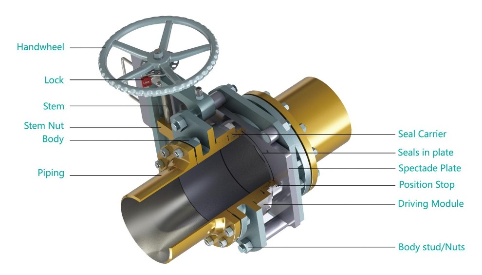
Part Description
|
Part Description |
Material |
|
Handwheel |
QT400-18 |
|
Stem |
A182 F6A |
|
Stem Nut |
Alloy Copper |
|
Body |
A350 LF2 |
|
Seal Carrier |
A350 LF2 |
|
Seals in plate |
Viton |
|
Spectade Plate |
A350 LF2+ENP |
|
Position Stop |
A193 B7 |
|
Driving module |
A350 LF2 |
|
Body stud/Nuts |
A193 B7/A194 2H |
|
Other materials and seal rings are available upon request |
|
Options
●Hand Wheel Extensions
●Locking Device
●Limit Switches
●Drain/Vent ports
●Spectacle Plate Covers to Protect Seals
●Compact Design (integral tapped end flange)
●Rain/Dust Shield
●Torque Limiter
Operation of Standard
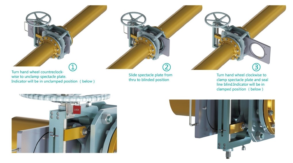
Mechanism Principle
In normal conditions, the blind valve's diversion hole is in contact with the pipeline, and the blind valve is in the open position. When maintenance is required, and the pipeline must be cut off, then loosen the stem of blind valve to move the flat end onto the pipeline, and make the blind valve turn to closed position from open position; tighten the stem and let the blind valve to perform sealing function and cut off the pipeline.
When the maintenance work is completed, loosen the stem and move the blind plate to the diversion hole and connected to the pipeline. The blind valve was turned to closed position from open one. Lock the stem, and seal it, the pipeline is now open, and the blind plate valve returns to the open position.
If you are interested in our products and want to know more details,please leave a message here,we will reply you as soon as we can.
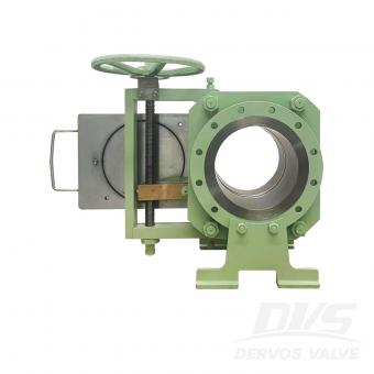
Line blind valve (eyeglass valve) is a kind of gate valve that cuts off gas medium manually, electrically or pneumatically or hydraulically. It is generally divided into electric blind valve, hydraulic blind valve, closed plug valve and electric open blind valve.
10" 150LB line blind valve is made according to ASME B16.34 standard. The valve body is made of A105. It has the structural characteristics of anti-drip. Its connection mode is RF. And it has turbine operation mode.
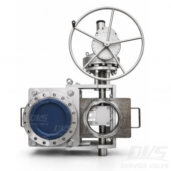
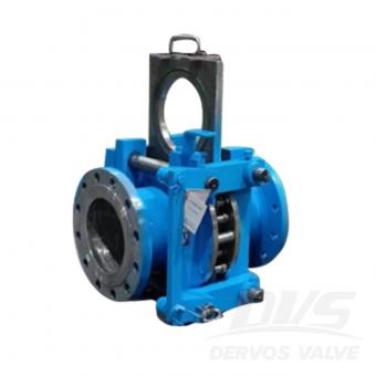
This DN400 PN40 forged slide blind valve provides positive isolation for steam pipelines and high-temperature industrial systems—physically blocking flow with a solid blind plate to ensure zero leakage during maintenance. Unlike conventional valves that rely on seats that can wear or degrade, this blind valve creates an absolute physical barrier, protecting personnel and preventing costly shutdowns. The sliding blind mechanism enables operators to switch between flow and isolation positions without depressurizing the line, significantly reducing downtime. Constructed from a one-piece forged A182 LF2 steel body, it delivers exceptional low-temperature toughness (down to -46°C) and reliable performance under PN40 pressure and high-temperature steam service up to 350°C. Designed to EN12516-1/2 and 100% pressure tested to EN12266-1/2, this valve features RF flanges per GOST 33259-Type B and a gear operator for smooth, high-torque actuation on large-diameter lines. It is a trusted choice for refineries, power plants, and industrial pipeline isolation where safety and reliability are paramount. Product Parameters Type Slide Blind Valve Size DN400 Pressure PN40 Connection RF Operation GEAR Body Material A182 LF2 Design Norm EN12516-1/2 Face to face Supplier Standards Flange dimension GOST 33259-Type B Test & Inspection Code EN12266-1/2 Temperature -46 ~ 350°C Applicable Medium Water, Oil and Gas Features • True Physical Barrier – Zero Leakage Isolation– Solid blind plate creates a true physical barrier. The one-piece forged LF2 body eliminates weld seams, ensuring structural integrity under PN40 pressure and thermal cycling. • Inline Operation Without Depressurization – Sliding mechanism enables switching without system blowdown. LF2 steel ensures reliable operation down to -46°C, ideal for cold climates and cryogenic steam conditions. • Gear-Operated for Large Diameters – High-torque gearbox ensures smooth and controlled operation for DN400 valves, even under demanding conditions. • Low-Temperature Toughness – ASTM A182 LF2 forged steel ensures reliable operation down to -46°C, ideal for cold climates and cryogenic steam conditions. Sliding Type Line Blind Valve Technical Drawing Dimension Checking Pressure Testing Painting Nameplate & Packing Inspection Report
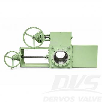
This 10-inch Class 150 Sliding Line Blind Valve provides absolute positive isolation for steam turbine pipelines and high-temperature industrial systems. Unlike conventional gate or ball valves that rely on seats subject to wear, the sliding blind mechanism creates a solid physical barrier—delivering zero leakage during maintenance and ensuring personnel safety. The gear-operated sliding plate allows operators to switch between flow and isolation positions without depressurizing the line, significantly reducing downtime. The drip-proof design prevents fugitive emissions, making it ideal for steam, oil, gas, and other critical services. Constructed from ASTM A105 forged carbon steel with RF flanges per ASME B16.5, the valve is designed to ASME B16.34 and tested to API 598. It offers reliable performance in applications up to 425°C (sealing dependent), combining durability, safety, and ease of operation. Product Parameters Type Sliding Blind Valve Size 10” Pressure 150LB Connection RF Operation Turbine Body Material A105 Design Norm ASME B16.34 Face to face Manufacturer Standard Flange dimension ASME B16.5 Test & Inspection Code API 598 Temperature -29 ~ 150°C (Higher temperature up to 425°C available with metal seat) Applicable Medium Water, Oil and Gas Features • Forged A105 Carbon Steel Body – Provides strength and durability for reliable performance in industrial pipeline service. • Drip-Proof Design – Prevents fugitive emissions and protects internal components, making it ideal for environmentally sensitive applications and steam turbine systems. • Absolute Physical Isolation – Solid blind plate provides true physical separation of the pipeline, ensuring safe maintenance without relying on sealing surfaces. • Online Switching – No Depressurization Required – Sliding mechanism allows switching between open and blind positions without pipeline blowdown, reducing downtime and media loss. • Gear-Operated for Large Diameters – High-torque turbine drive enables smooth and controlled operation for large valves, even under demanding conditions. Slide Type Line Blind Valve Technical Drawing Dimension Checking Pressure Testing Painting Nameplate & Packing Inspection Report
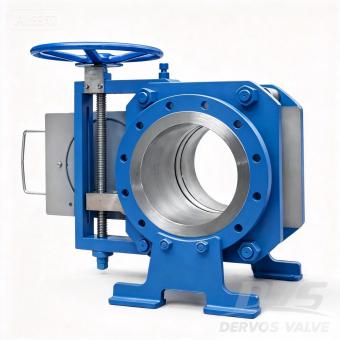
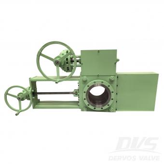
Introduction This 10" Class 300 Sliding Line Blind Valve provides absolute positive isolation for medium‑ to high‑pressure pipelines, combining the reliability of a solid physical barrier with the simplicity of manual screw‑operated actuation. Unlike conventional valves that rely on seats prone to wear, the sliding blind mechanism creates a true physical barrier, ensuring zero leakage during maintenance without the need for system depressurization. This significantly reduces downtime and enhances personnel safety. The manual screw‑operated design offers precise, controlled movement of the blind plate, with inherent self‑locking capability to maintain position under pressure—ideal for applications where electric or pneumatic power may not be available or preferred. Constructed to ASME B16.34 with RF flanges per ASME B16.5, this valve is available in forged carbon steel (A105), stainless steel, or alloy materials to suit your service conditions. Each unit is 100% pressure tested to API 598. This 10" Class 300 configuration is a popular choice for steam, oil, gas, and chemical pipelines. Other sizes from 1" to 60" and pressure classes up to Class 2500 are available as part of our full line blind valve series. THD-Slide Cutout Features 1.Manual Screw‑Operated with Self‑Locking Precision screw drive allows smooth, controlled positioning of the blind plate. The self‑locking mechanism maintains position under pressure without additional braking devices. 2.Absolute Physical Isolation Solid blind plate creates a true barrier, ensuring zero leakage during maintenance—unlike seat‑dependent valves that can wear or degrade over time. 3.Inline Operation Without Depressurization Sliding mechanism enables switching between flow and blind positions without system blowdown, reducing downtime and product loss. 4.10″ Class 300 – The Optimal Balance Offers higher pressure capability than Class 150 while remaining more economical than Class 600, making it a versatile choice for a wide range of industrial applications. 5.Forged Carbon Steel Construction A105 forged body provides high strength, impact resistance, and reliable performance under thermal cycling. 6.Tested to API 598 100% hydrostatic and pneumatic testing ensures leak‑tight performance before shipment. Standard Specifications Parameter Specification Type Sliding Line Blind Valve Size 10″ (DN250) Pressure Rating Class 300 (PN50) Connection RF Flange, ASME B16.5 Operation Manual Screw-Operated (Self-locking) Body Material A105 Forged Carbon Steel (other alloys available) Seal / Seat Material Metal-to-Metal (Stainless Steel + Graphite) Design Standard ASME B16.34 Face-to-Face Dimension Per ASME B16.10 or manufacturer standard Test & Inspection API 598 (100% hydrostatic & pneumatic) Temperature Range -29°C to +425°C (depending on sealing) Applicable Media Steam, Oil, Gas, Water, Hydrocarbons Application Pipeline isolation, refineries, petrochemical plants, power generation Technical Drawing Flexible Design Options Tailored Configurations for Demanding Applications Beyond the base model, this line blind valve can be customized for high-temperature service, fire-safe requirements, and zero-emission (drip-proof) operation. For installations where space is at a premium, a compact variant is available, offering the same robust isolation performance in a reduced footprint. Simplified Seal Maintenance– No Disassembly Required Seals are integrated into the spectacle plate, allowing operators to inspect or replace them without dismantling the valve. Condition checks can be performed while the valve remains in service, before any position change, ensuring seal integrity is verified before operation. Low Total Cost of Ownership The valve’s streamlined, heavy‑duty construction delivers reliable positive shut‑off with minimal upkeep. Its unique actuation mechanism allows a single operator to quickly and safely isolate the pipeline—no tools required—reducing labor time and simplifying maintenance procedures. Options ●Hand Wheel Extensions ●Locking Device ●Limit Switches ●Drain/Vent ports ●Spectacle Plate Covers to Protect Seals ●Compact Design (integral tapped end flange) ●Rain/Dust Shield ●Torque Limiter
Copyright © 2015-2026 DERVOS VALVE CO.,LTD.All Rights Reserved Blog / Sitemap / XML / Privacy Policy