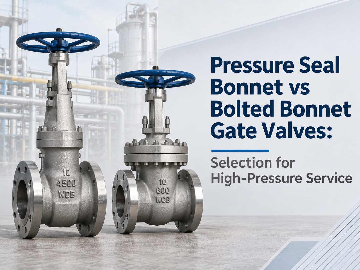
A pressure-seal bonnet is usually the stronger candidate for very high-pressure, high-temperature service because internal pressure increases the sealing load at the body-bonnet joint. A bolted bonnet relies primarily on bolt preload to compress its gasket and is often simpler to inspect and disassemble. That does not create a universal pressure-class cutoff. A Class 600 valve may use a pressure seal, while a bolted-bonnet design may be available at a higher class. The correct choice depends on the applicable pressure-temperature rating, valve size, material, thermal cycles, start-up conditions, maintenance plan, and the manufacturer’s qualified design. Quick Selection Answer Choose a pressure-seal bonnet when the service combines high pressure with high temperature, repeated thermal loading, or a critical external-leakage consequence, and the plant can support its more specialized maintenance procedure. Choose a bolted bonnet when the approved valve design satisfies the full pressure-temperature envelope and familiar disassembly, gasket replacement, and general maintenance access have greater value. Do not use the bonnet style to decide the valve function. Gate, globe, and check valves can all be made with pressure-seal constructions, but they perform different jobs in the system. How Does a Bolted Bonnet Work? In a bolted-bonnet valve, a flanged joint connects the bonnet to the body. Studs or bolts apply the initial clamping force, compressing a gasket between the mating faces. The bolting, flange geometry, gasket, surface finish, assembly method, and temperature all affect joint integrity. As internal pressure rises, pressure-generated forces tend to separate the body and bonnet. The joint must retain enough gasket compression after pressure, temperature change, bolt relaxation, and thermal expansion are considered. Correct tightening sequence and controlled preload therefore matter. The main practical advantage is familiarity. Maintenance teams can see and access the external bolting, and the disassembly sequence is generally straightforward. However, the joint may become large and heavily bolted as pressure, size, and design load increase. How Does a Pressure-Seal Bonnet Work? A pressure-seal bonnet uses an internal gasket and a retaining system rather than a conventional large external body-bonnet flange. Exact details vary, but common designs use a bonnet or cover, pressure-seal gasket, spacer or thrust ring, and segmented retaining ring inside the body neck. Process pressure acts on the bonnet assembly and forces the sealing elements against their contact surfaces. As pressure increases, the body-bonnet sealing load also increases. This is why the design is described as self-energizing or pressure assisted. Self-energizing does not mean self-assembling. At zero or low pressure, the process has not yet created its full sealing force. The initia...
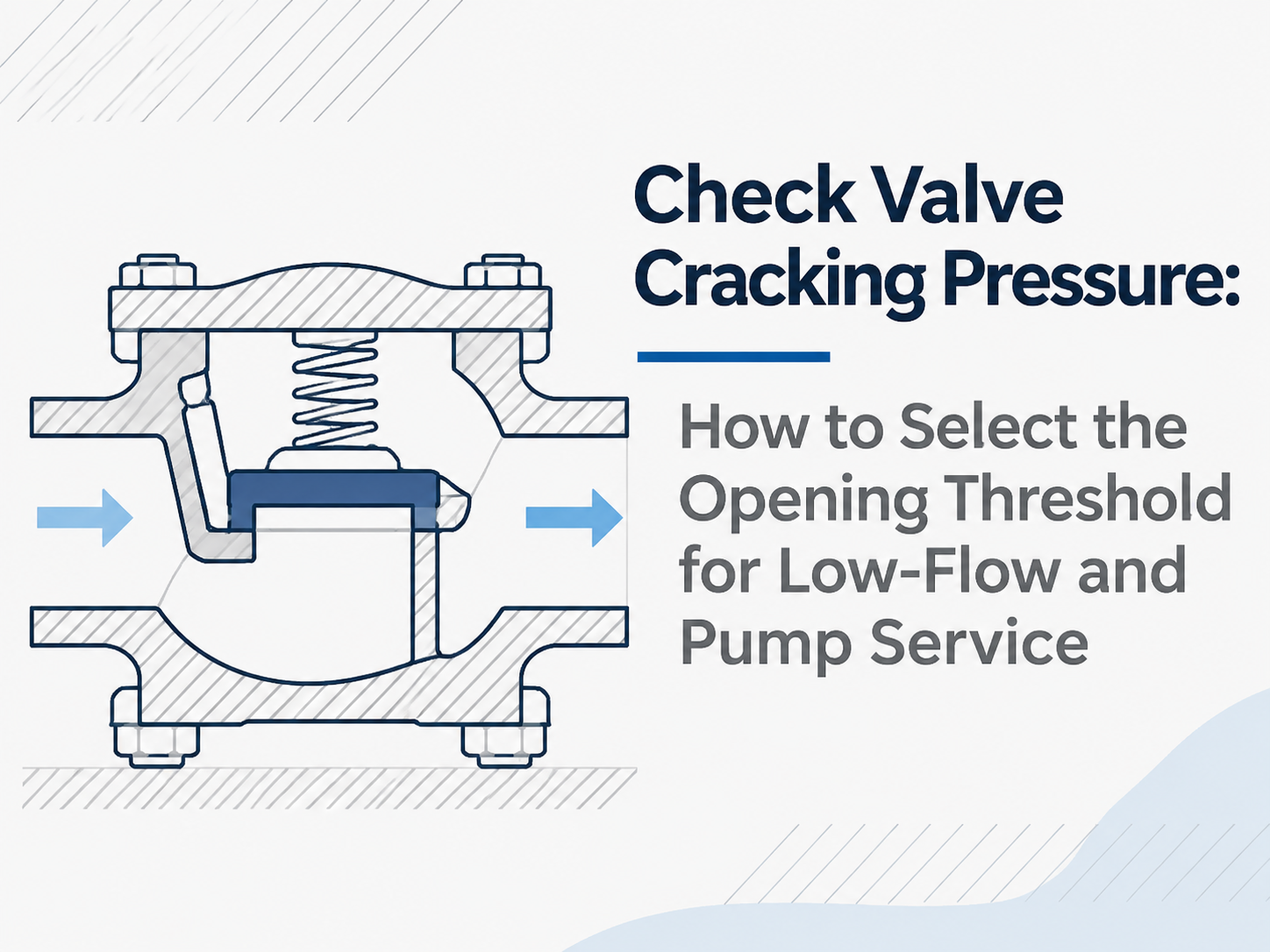
A check valve can begin to pass fluid and still be far from a stable open position. Check valve cracking pressure is therefore the threshold for first detectable flow, not the full-open pressure drop or proof of reliable minimum-flow operation. For low-flow and pump service, the opening threshold is acceptable only when the system can exceed it in the worst forward-flow case. The selection must then pass three separate checks: stable valve travel at minimum flow, acceptable pressure loss at normal and maximum flow, and timely closure when the pump stops. Start with the Worst Available Differential Pressure Parker defines cracking pressure as the upstream pressure at which detectable flow is measured, while Swagelok notes that first flow does not mean the valve is fully open. The relevant system value is not pump discharge pressure alone, but the pressure difference across the valve when it must open. For an initial screen: Available opening ΔP = minimum upstream pressure at the valve − maximum downstream pressure at the valve If the pressures come from remote points, correct them for elevation and line losses. Evaluate the least favorable credible case, such as a variable-speed pump starting at low speed or a standby pump opening against a live common header. The maximum guaranteed cracking pressure of the offered valve should be below this available ΔP, with an engineering allowance for manufacturing tolerance, temperature, orientation, deposits and measurement uncertainty. There is no defensible universal allowance. A nominal value alone is insufficient because catalog cracking pressure may be specified as a range, and a valve left idle may initially require a higher differential than it does after cycling. Low Cracking Pressure Does Not Solve Low-Flow Instability After the closure member lifts, more differential pressure and flow force are needed for stable travel. An oversized valve may crack open but hover near the seat because velocity is too low, causing clicking, flutter, impact and accelerated wear. Swagelok’s service guidance identifies excessive spring cracking pressure and excessive valve size as possible causes of chatter near the threshold. Size from the operating envelope rather than automatically matching the pipe diameter. Ask the supplier to evaluate three points for the exact size, spring and trim: Operating point Required evidence Minimum continuous flow Stable-open position, minimum stable flow or velocity, and corresponding ΔP Normal flow Model-specific pressure-drop curve or validated flow coefficient Maximum flow Peak ΔP, velocity limits, erosion risk and acceptable travel Cracking pressure answers “When does motion begin?” The flow curve and stable-flow limit answer “Will the valve remain open without damaging itself?” Pump Opening and Pump Shutdown Are Different Design Cases At s...
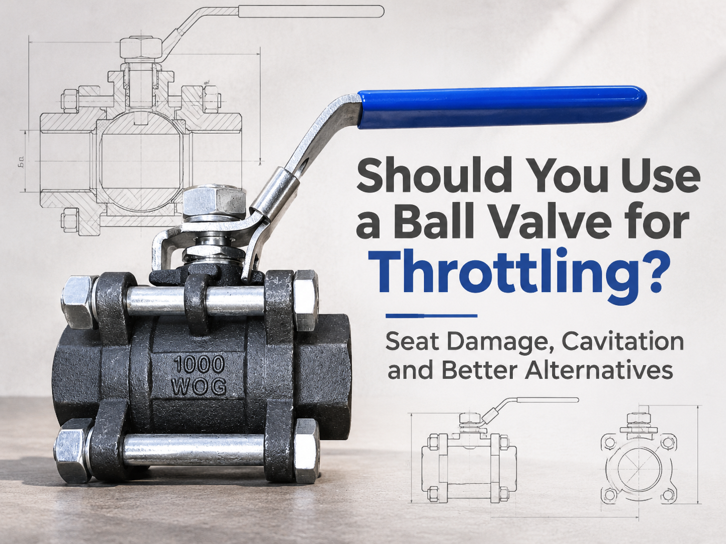
A standard on-off ball valve should not be the default choice for continuous throttling. It can restrict flow, but that does not make it a control valve. Holding it partly open can expose the seat to a concentrated high-velocity jet, produce unstable control and, in liquid service, create cavitation. Brief restriction during start-up or shutdown may be acceptable if the manufacturer permits it. Regular modulation requires a valve designed and sized for that duty. A Part-Open Ball Puts the Seat in the Flow Path When a standard ball valve is fully open, the bore provides a relatively straight flow path. As the ball rotates toward closed, the opening becomes a narrow, changing shape. Velocity rises through this restriction, and the emerging jet can pass close to the downstream seat edge and body cavity. That matters because the seat performs the shutoff function. A soft seat may deform, cut or erode under high velocity, heat and entrained solids. A metal seat may tolerate harsher conditions, but hardness alone does not provide a suitable control characteristic or prevent local erosion. Damage often appears later as increased shutoff leakage, even though the valve still moves normally. Control quality is another limitation. A conventional full-port ball may pass a large increase in flow over a small change in travel once it begins to open. The actuator can therefore hunt around a narrow angle instead of positioning smoothly across a useful range. A positioner cannot correct an unsuitable valve characteristic. Cavitation Depends on the Local Pressure, Not Just Line Pressure Cavitation is possible when liquid accelerates through the restriction and its local pressure falls below the liquid's vapour pressure. Vapour bubbles then form. If pressure recovers above vapour pressure downstream, the bubbles collapse and release damaging energy near the valve or downstream pipe. Ball valves are generally high-recovery valves: much of the pressure lost at the narrowest flow area is recovered downstream. That means the minimum internal pressure can be considerably lower than the measured outlet pressure. A moderate-looking inlet-to-outlet pressure drop may therefore hide a more severe pressure dip inside the valve. Noise resembling gravel, vibration and rough pitting are warning signs, but sound alone is not a design method. The evaluation needs minimum, normal and maximum flow; upstream and downstream pressure at each case; fluid temperature and vapour pressure; density; solids content; valve size; and the manufacturer's pressure-recovery and sizing data. If downstream pressure remains below vapour pressure, the condition is flashing rather than cavitation and requires a different damage assessment. A Ball Valve Can Throttle When It Is a Control Valve A V-port or segmented ball introduces a shaped opening that gives a more predictable relationship between travel and flow. Correctly sele...
Payment:
30% T/T When Order, 70% T/T Before ShipmentProduct Origin:
ChinaColor:
CustomizationShipping Port:
Shanghai ChinaLead Time:
35~60 days Ex Works After Order ConfirmationMaterial:
GGG50Method of Operation:
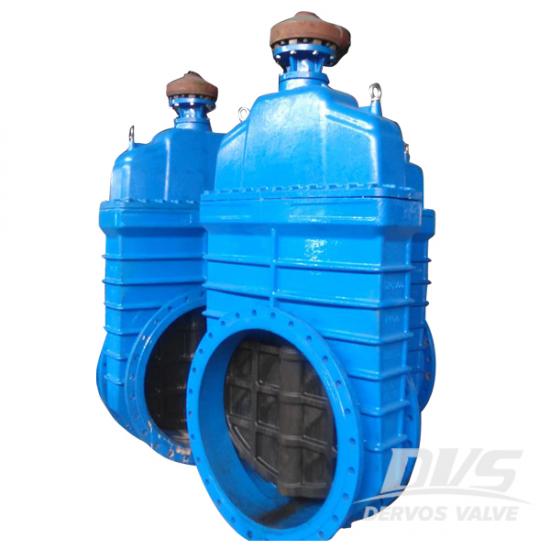
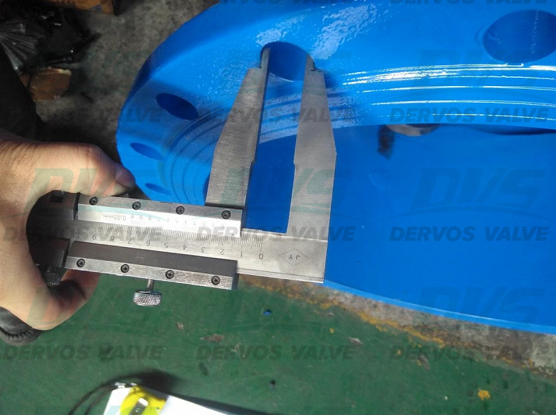
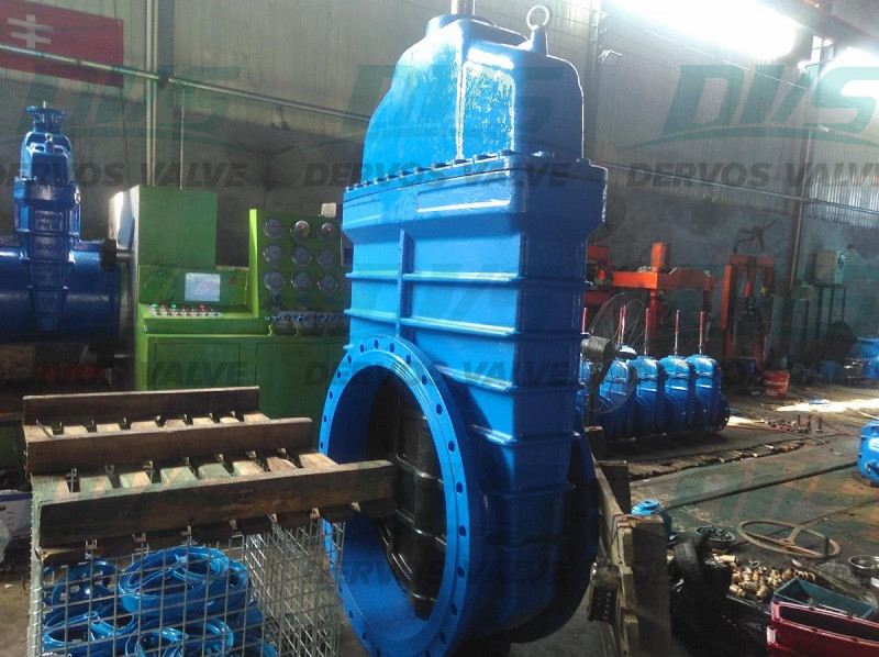
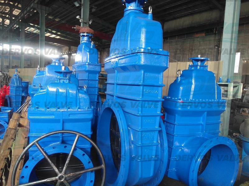
GearboxResilient gate valve F4, GGG50 Body Bonnet, GGG50 Disc, SS410 Stem, EPDM Seat, Brass or Bronze Stem Nut Gearbox Operation Raised Face DN1000 PN10 DIN 3352 Design Standard, Face to face DIN 3202 F4, DIN 2532 Flanged end, PN10 Working Pressure,non-rising stem
Quick Detail
|
Type |
Resilient GateValve |
|
Size |
DN1000 |
|
Design Pressure |
PN10 |
|
Construction |
BB, Non rising Stem |
|
ConnectionType |
RF |
|
OperationType |
Gearbox |
|
Body Material |
GGG50 |
|
WedgeMaterial |
GGG50 |
|
Stem Material |
SS410 |
|
Design Code |
DIN 3352 |
|
Face to Face Dimension |
DIN 3202 F4 |
|
Origin |
China |
If you are interested in our products and want to know more details,please leave a message here,we will reply you as soon as we can.
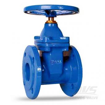
The DN80 PN16 cast iron gate valve has face to face dimension as per DIN3202 F4 or DIN3202 F5. This GG25 gate valve is designed with resilient seat, non rising stem, bb, RF flange, suitable for water treatment application. Quick Detail Type Gate Valve Nominal Diameter DN 80 Nominal Pressure PN 16 ConstructionType Non-rising stem, Bolted Bonnet, Resilient Seat ConnectionType Flanged OperationType Handwheel Operation Body Material Cast Iron GG25 TrimMaterial Cast Iron Wedge, SS420 Stem, EPDM Seat Design Code DIN 3352 End to End Code DIN 3202 Flange Dimesion DIN 2501 Medium Water Origin China Design Feature 1.Resilient seat for good sealing performance 2.Low flow resistance and small pressure drop 3.Non-rising stem for installation space is limited 4.No limitation for flow direction of medium 5.Epoxy painting available for internal and external part of the valve for anti corrosive function Company Brief Introduction Specializing in valve industry over 10 years, Dervos becomes the leading vendor of gate, globe, check, ball, butterfly, plug valves and strainers. We serve oil and gas user such as LUKOIL, MOL, YPF with local partners. Dervos show its advantages in: 1. Our partnerships with tens of stable suppliers allow us to provide customers with a wide range of high-quality products at a competitive price. 2. Each order is under strict quality control with inspection reports before delivery. 3. We value delivery time as much as our customers do. With the powerful purchasing system, we follow each order closely to secure on-time delivery. 4. One-stop solutions will be offered in a timely manner
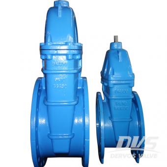
The ductile iron gate valve has GGG50 body material and EPDM soft seat. The valve is designed with non-rising stem, RF connection and manual operation, used in fire water. Quick Detail Type Gate Valve Size DN300, DN400 Design Pressure PN10 Construction Non-rising Stem, Soft Seat ConnectionType Flange OperationType Handwheel Operation Body Material GGG50 TrimMaterial Stem 2Cr13, EPDM Seat Medium Water Origin China Hydrostatic Pressure Test Dimension Checking Packing
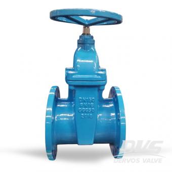
The gate valve is made of ductile iron GGG50 . The valves disc is rubber-packed to get excellent sealing effect by the rubber's resilient deformation. Non-rising resilient seated gate valves solve the problem in general gate valves such as leakage, rusting etc. And it also saves space.
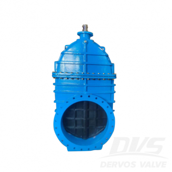
DN800 PN10 gate valve is made according to DIN standard. The valve body is made of GGG50. It has the structural characteristics of F4 drinking water soft gate. Its connection mode is RF, and it has gear operation.
Copyright © 2015-2026 DERVOS VALVE CO.,LTD.All Rights Reserved Blog / Sitemap / XML / Privacy Policy