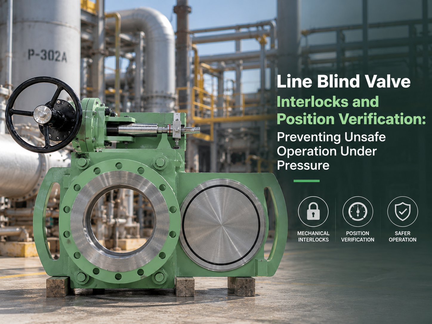
A line blind valve creates positive isolation only after the solid plate is correctly positioned, fully restrained and capable of withstanding the process pressure. The dangerous part is the transition between the open and blinded states: many designs temporarily release the clamping force or expose part of the line while the plate moves. An interlock must therefore control an isolation sequence, not merely prevent the actuator from starting. A “closed” lamp, a limit-switch signal or a zero-pressure indication is useful evidence, but none of them independently proves that the line is safe to open. Why Operating Sequence Matters More Than Actuator Type Whether the line blind is manual, electric or hydraulic, it should not move until the process has been isolated, depressurized and drained. A powered actuator makes remote operation possible, but it also allows an incorrect command to be executed rapidly and from a location where the operator cannot see a release. A robust sequence normally requires: 1. Upstream and downstream block valves are closed and locked or otherwise secured. 2. The trapped section is vented or drained to a suitable disposal system. 3. Pressure has fallen below the project-defined permissive value. 4. A field operator or independent authorization confirms that the isolation arrangement is correct. 5. The line blind clamping mechanism is released. 6. The plate moves completely into the open or blind position. 7. The mechanism reclamps and mechanically secures the plate. 8. Final position and clamping status are recorded before process conditions are restored. This sequence matters because closing the adjacent valves does not remove trapped pressure. A blocked drain, leaking upstream valve, vaporizing liquid or thermal expansion can repressurize the cavity after an initial pressure reading. AIG therefore recommends upstream isolation, bleed and pressure indication for line blind installations, with double block and bleed considered where a large hazardous inventory could be released. It also identifies pressure-sensing interlocks, controlled keys and secondary isolation verification as possible protection layers. What Position Feedback Actually Proves Position verification should answer three separate questions: · Is the solid or open plate in the intended location? · Is the plate fully clamped and mechanically retained? · Is the surrounding process condition safe for movement? These are different states and should not be represented by one shared switch. A limit switch normally confirms that the component driving the switch has reached a calibrated endpoint. It does not automatically prove that the blind plate followed the drive mechanism, that the plate is centred between the seats, or that the clamping load is adequate. A loose cam, bent bracket, damaged linkage or incorrectly adjusted switch can produce...
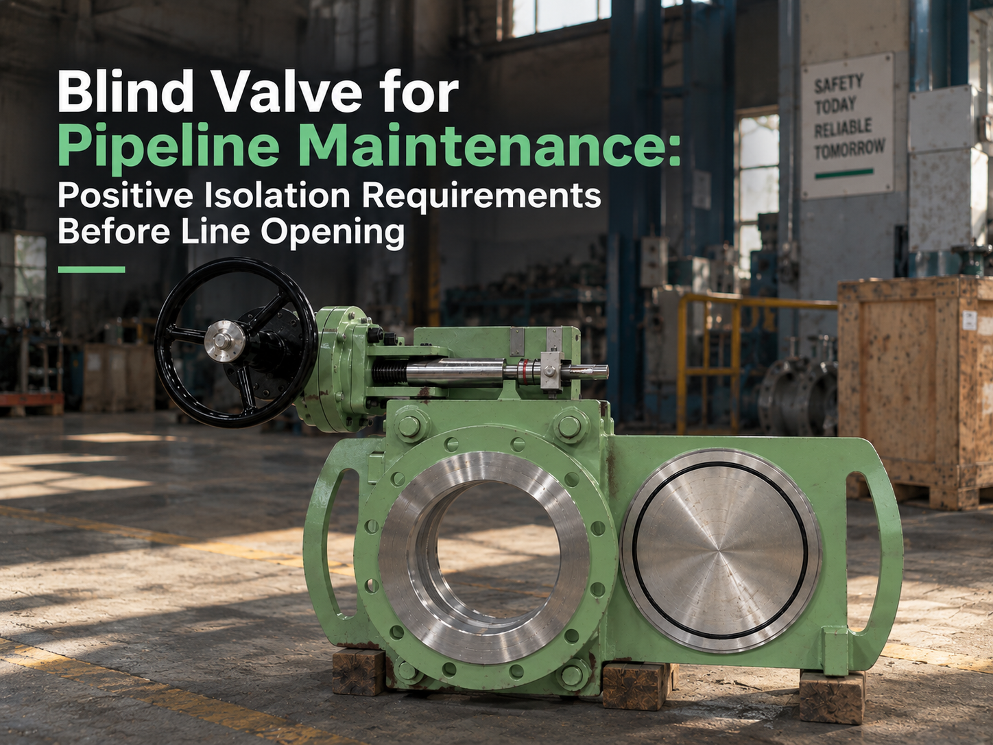
Before a pipeline is opened, a blind valve should be treated as one part of an isolation system, not as a permit by itself. Its value is that it can place a visible physical barrier in the line, but that barrier only becomes meaningful when the site has also isolated, depressurized, drained, vented, locked, tagged, tested, and verified the correct section of piping. Line opening is the moment when weak isolation becomes real. A closed valve may pass. A bleed point may be plugged. A drawing may be outdated. Liquid may remain trapped in a low point. Gas may migrate from an unexpected connection. This is why positive isolation for pipeline maintenance has to be judged as a chain of proof, not a single valve feature. The Isolation Boundary Must Be Proven on the Drawing and in the Field The first requirement is knowing exactly what is being isolated. Maintenance teams usually start from the P&ID or isolation plan, but the field verification is just as important. Tie-ins, bypasses, drains, vents, sample points, small-bore branches, equalizing lines, instrument connections, and thermal relief paths can all create energy routes around the expected isolation point. A blind valve installed in the correct location can give strong physical isolation. Installed on the wrong side of a branch connection, it may protect the main line while leaving the work face exposed to pressure or hazardous material from a side path. That is not a valve failure; it is an isolation boundary failure. Before line opening, the isolation plan should identify the upstream and downstream sources, the section to be opened, all possible re-pressurization routes, and the exact valve position required. The field check should confirm tag numbers, flow direction, blind position, locking status, and whether the valve can be seen and reached safely. Positive Isolation Is More Than Seat Leakage A blind valve differs from a normal shutoff valve because it uses a solid blind plate, spectacle plate, or sliding/swinging blind mechanism to block the bore. This reduces reliance on seat tightness alone. For maintenance work involving flange breaking, equipment opening, hot work, confined-space entry, or hazardous media, that physical barrier can be more defensible than a closed gate, globe, or ball valve. Still, the phrase “positive isolation” should not be used loosely. The blind must be in the correct position, fully seated, mechanically restrained, locked or tagged according to the site procedure, and confirmed by position indication that maintenance personnel can understand. If the mechanism is stiff, partly engaged, poorly marked, or difficult to verify from the work area, the valve’s theoretical advantage becomes weaker. The seal arrangement also matters. Some line blind valves rely on resilient seals, graphite seals, metal seating surfaces, or combined sealing designs depending on temperature, pressure, and ...
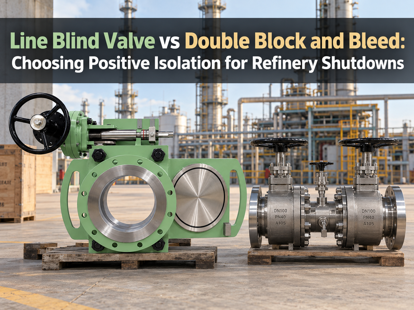
In refinery shutdowns, the choice between a line blind valve and double block and bleed is not a contest between one safe method and one unsafe method. Both can be valid isolation methods, but they control risk in different ways. A line blind valve creates isolation by moving a solid blind plate into the pipeline bore. The isolation is visible and mechanical. A double block and bleed arrangement isolates by closing two barriers and opening a bleed or vent between them, so trapped pressure or leakage can be released or monitored. The engineering question is not only “which one seals better?” It is “what work will happen after isolation, and how much reliance can the site accept on valve seats, bleed monitoring, and procedure control?” Shutdown Work Changes the Isolation Standard Routine instrument work, sampling maintenance, or short inspection tasks may justify a different isolation method from hot work, vessel entry, flange breaking, or long-duration turnaround maintenance. In a refinery, the same hydrocarbon line may be low-risk in one task and high-risk in another because the exposure changes. A DBB arrangement is useful when the work needs fast, verifiable valve isolation without moving a blind plate into the bore. The bleed point gives operators a way to confirm whether pressure is trapped between the isolation points or whether one of the seats may be passing. For many operating teams, that makes DBB practical for frequent or temporary isolation where breaking containment would add more work and more exposure. A line blind valve becomes stronger when the job needs visible physical separation from a live or potentially live system. If the isolated equipment will be opened, entered, welded, cleaned, or left out of service during a shutdown window, a solid blind plate reduces dependence on seat tightness. The valve still needs proper operation, locking, marking, and testing, but the core barrier is no longer only a seating surface. Where DBB Earns Its Place DBB is attractive because it can reduce downtime. A compact DBB valve or a two-valve DBB arrangement can isolate, bleed, and verify without removing a spool or installing a separate blind flange. For refinery units with many small-bore connections, drains, vents, sampling points, or instrument take-offs, that speed matters. The risk with DBB is that its safety case still depends on seat integrity, correct bleed routing, pressure monitoring, and disciplined lockout practice. If the bleed is not routed to a safe location, it may create a release hazard. If operators close two valves but do not prove the bleed, the system may only look isolated. If the valves have seat damage from coke, catalyst fines, thermal cycling, corrosion, or debris, the bleed point may reveal leakage rather than eliminate it. This is why DBB should be described clearly in the shutdown plan. Does the project mean two separate inline isolation valves with a drain...
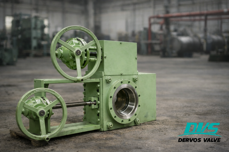
An oil terminal operator in South Africa, handling multiple light petroleum products such as HSD, MA, and JET-A1 within its pipeline system, encountered the following key challenges:
● Volatile and complex media: Aviation fuels such as JET-A1 require extremely high sealing performance; even minor leakage poses significant safety risks.
● Frequent media switching: Reliable physical isolation is required during product changeover. Conventional valves cannot achieve absolute shut-off.
● Insufficient sealing performance: Standard gate valves and ball valves present a risk of internal leakage after prolonged service.
● Strict safety requirements: The client specified a clear requirement for “zero visible leakage.”
To address these operating conditions, Dervos Valves supplied a Slide Blind Valve, with the following key configurations:
Design Type: Slide Blind (Spectacle Blind / Line Blind)
● Switching between a solid plate and a spacer enables complete shut-off or full flow.
● Provides visual and verifiable positive isolation, meeting high safety requirements.
Sealing Design: Drip-tight Construction
● Effectively prevents leakage and evaporation of light hydrocarbons.
● Suitable for stringent sealing requirements of aviation fuel service.
Pressure Rating and Standards:
● Class 150, in accordance with ASME B16.34
● Flanged connection: Raised Face (RF)
Material: ASTM A105 Forged Steel
● Offers high mechanical strength and pressure resistance.
● Well-suited for petroleum service, balancing cost efficiency and reliability.
Operation: Worm Gear (Turbine Drive)
● Suitable for large diameter (10") applications, reducing manual effort.
● Enhances operational stability and safety during switching.
In actual operation, the slide blind valve enabled reliable physical isolation between different petroleum products, ensuring a clearly verifiable disconnected state during media switching. This fundamentally eliminates the risk of internal leakage associated with conventional valves.
The drip-tight design effectively controlled evaporation and leakage when handling light hydrocarbons such as HSD, MA, and JET-A1, significantly improving on-site safety performance. In addition, the worm gear operation provided smoother and more controlled switching, reducing manual effort and minimizing the risk of operational errors, even in large-diameter applications.
Overall, the solution not only met the client’s stringent requirements for high sealing integrity and safety, but also improved the operational stability and maintenance reliability of the pipeline system.
If you are interested in our products and want to know more details,please leave a message here,we will reply you as soon as we can.
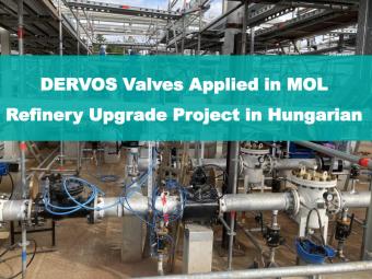
The refinery of MOL, located in Hungary, requires regular ball valve and check valve replacements to maintain optimal performance. As a trusted check and ball valve supplier of MOL, DERVOS continues to provide ball valves for their operations. In this project, DERVOS supplied a batch of high-performance ball valves and check valves for fluid control in oil and gas applications. They required various types and specifications of ball and check to meet the operational and sealing requirements of different pipeline systems.
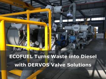
In 2017, DERVOS contributed to an innovative environmental initiative led by ECOFUEL, an emerging canadian player in clean technology. This groundbreaking project aimed to produce sustainable diesel from solid waste, setting a precedent in green energy solutions. DERVOS is proud to have provided 136 sets of premium valves to support this pioneering effort.
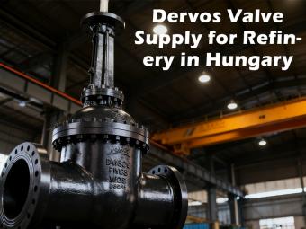
Project Background In 2024, DervosValve was selected as a trusted valve supplier for a refinery project in Hungary. The client required large-sized industrial valves capable of handling complex and high-pressure oil and gas media. With years of engineering experience and proven track records in the energy sector, Dervos was chosen to provide a complete valve solution tailored to the refinery’s operational needs. Scope of Supply ● 10 pcs Gate Valves ● 9 pcs Check Valves All valves were designed and manufactured according to API and ASME standards, ensuring compliance with international refinery safety and performance requirements. Product Design & Technical Highlights The supplied valves feature bolted bonnet design, flexible wedge, and rising stem with yoke support, which enhance sealing reliability and facilitate maintenance. Their large-scale structure was customized to fit the refinery’s pipeline system, allowing smooth fluid control and stable operation under high temperature and pressure. Performance in Refinery Conditions Refinery environments involve frequent temperature fluctuations and medium impurities. Dervos valves demonstrated outstanding sealing performance, corrosion resistance, and mechanical strength, ensuring long-term stability with minimal maintenance requirements. The bolted bonnet design also makes disassembly and inspection more convenient during scheduled shutdowns. Why the Client Chose Dervos The Hungarian client valued Dervos for: ● Proven experience in oil & gas valve solutions ● Strict material traceability and quality control system ● Flexible customization capabilities for large valve dimensions ● On-time delivery and complete documentation support Throughout the project, our technical and logistics teams worked closely with the client’s engineers, ensuring each valve was tested, packaged, and delivered to meet project timelines and refinery installation standards. Customer Feedback & Project Outcome After installation and commissioning, the refinery reported stable operation and precise flow control performance. The valves’ large design and robust construction fully met system pressure and flow requirements. The client expressed satisfaction with both the quality and Dervos’ technical responsiveness, laying a solid foundation for future cooperation. Conclusion This successful refinery project in Hungary once again highlights Dervos’ ability to deliver reliable, large-size valve solutions for the oil and gas industry. We continue to serve our global partners with precision engineering, professional service, and long-term reliability.
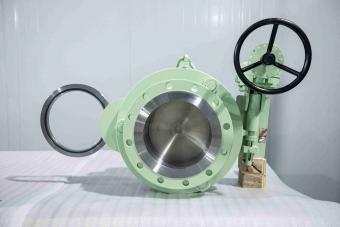
Zimbabwe National Oil Infrastructure Company (NOIC) Tank Farm Project This article is based on a tank farm project of the Zimbabwe National Oil Infrastructure Company (NOIC), focusing on practical challenges in pipeline isolation and maintenance switching, including flammable media, the requirement for pressurized operation, and high reliability under outdoor conditions. The solution involves a 10" 150LB swing type line blind valve, designed in accordance with ASME B16.34, with WCB cast steel body and metal sealing tested to API 598 zero leakage standards. Combined with worm gear operation and an anti-misoperation mechanism, the valve enables positive isolation switching without depressurization or shutdown. The implementation effectively improves operational safety, enhances maintenance efficiency, and reduces downtime losses. This case provides practical reference for engineers involved in pipeline isolation, valve selection, and online maintenance in the oil & gas industry. Project Background ● End User: Zimbabwe National Oil Infrastructure Company (NOIC) ● Installation Location: Petroleum storage terminal, Zimbabwe ● Medium: Petroleum ● Operating Requirement: The pipeline must reliably switch between normal operation and maintenance conditions, with strict requirements for safe isolation and zero leakage shut-off. Challenges Faced by the Client 1) Flammable Medium with High Safety RequirementsThe transported medium is petroleum. Any leakage may result in serious safety incidents. Therefore, high sealing integrity and operational reliability are required. 2) Requirement for Isolation Under PressureConventional valves cannot provide positive isolation without depressurization during maintenance. Depressurization leads to operational interruption, product loss, and additional restart costs. 3) Outdoor Installation with High Reliability DemandThe valve is installed in an outdoor station. It must withstand site environmental conditions and ensure stable operation with controlled risk of misoperation over long-term service. Solution To address the above conditions, Dervos Valve supplied a 10" 150LB swing type line blind valve with the following key design features: 1) Design Standard and MaterialThe valve is designed and manufactured in accordance with ASME B16.34. The body material is WCB cast carbon steel, suitable for petroleum service conditions, with a temperature range of -29°C to 150°C, offering adequate corrosion resistance and mechanical strength. 2) Sealing PerformanceThe sealing pair adopts a precision-machined soft sealing structure, tested in accordance with API 598. It achieves reliable zero leakage under petroleum service conditions, ensuring safe pipeline isolation. 3) Swing Type Blind StructureThe swing blind plate allows switching between flow and blind positions without pipeline disassembly or depressurization. This enables rapid transition and solves the limitation of conventional valves in achieving online positive isolation. Swing Type Blind Technical Drawing 4) Operation and Safety DesignEquipped with a worm gear operator and anti-misoperation device, the valve ensures smooth manual operation with clear position indication, minimizing the risk of incorrect operation in field conditions. Implementation Results After commissioning, the solution delivered the following benefits: 1) Reliable Isolation PerformanceThe valve meets API 598 leakage requirements. No leakage has been observed during operation, ensuring safe pipeline performance. 2) Improved Maintenance EfficiencyThe swing type structure enables online isolation without depressurization. Maintenance time is significantly reduced, minimizing production interruption. 3) Controlled Operational SafetyClear blind position indication and anti-misoperation design reduce risks for field operators, aligning with safety management practices in oil & gas facilities. Conclusion In this project, Dervos Valve provided a swing type line blind valve solution that achieves safe isolation under continuous operation in petroleum service. The solution ensures long-term sealing reliability and meets the project's requirements for safety, reliability, and operational efficiency in national oil infrastructure applications.
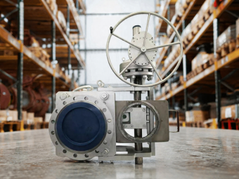
In an industrial steam system project in Hungary, a DN400 PN40 sliding blind valve was applied to achieve safe isolation and zero leakage shut-off under high-temperature conditions. What Challenges Are Commonly Encountered in Steam System Maintenance? In industrial steam systems, maintenance activities often face several practical challenges.In this project, the main issues included: ● The process medium was steam, with an operating temperature of approximately 250°C and a design temperature range from -39°C to 350°C, requiring the equipment to withstand both high-temperature and low-temperature conditions. ● The steam system required high sealing performance; conventional valves are prone to sealing failure under high-temperature steam conditions. ● During pipeline maintenance, safe isolation was required; traditional isolation methods could not achieve blind switching without depressurization. ● The valve was exposed to outdoor conditions, with ambient temperatures as low as -39°C, requiring high structural reliability and safe operation. How Can These Challenges Be Addressed in High-Temperature Steam Pipeline Systems? Based on the actual service conditions and technical requirements, Dervos Valve provided a customized DN400 PN40 forged sliding blind valve solution: 1. Material and Standards Designed in accordance with EN 12516, the valve body is made of ASTM A350 LF2 forged steel, offering both low-temperature impact toughness down to -40°C and stable strength at temperatures up to 350°C, suitable for wide temperature fluctuations. 2. Sealing Design The sealing pair adopts Stellite hardfacing with precision-machined metal sealing surfaces, meeting EN 12266-1 Leakage Class A requirements.Reliable zero leakage performance is maintained under 250°C saturated steam and thermal cycling conditions. 3. Structure and Operation The full-bore design reduces flow resistance, while a gear-operated mechanism ensures smooth operation for large-size PN40 valves. The sliding blind structure enables inline isolation switching without depressurization or pipeline disassembly, combined with: ● Mechanical interlock to prevent misoperation ● Visual position indication This significantly improves maintenance safety. Project Performance Since commissioning, the valve has completed more than 20 pressurized isolation operations, with sealing performance consistently meeting Class A requirements and no internal or external leakage observed. The switching time for each isolation operation is controlled within 10 minutes, significantly reducing maintenance time compared to traditional methods involving depressurization and manual blind insertion. Designed in accordance with EN 12516, the valve has an expected service life of 30 years, contributing to a substantially lower total lifecycle maintenance cost.
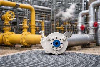
Project Type: Safety upgrade of an in-service high-pressure pipelineClient: A major oil & gas company in Russia (Siberia region)Application: Isolation and maintenance blind-off for high-temperature steam / hot oil pipelinesPressure Rating: 600LB (Class 600)Core Product: F22 Swing-Type Line Blind Valve (note: swing-type retained; see clarification below)Commissioning: Q3 2024Data Collection Period:12 months 1. Challenges Faced by the Client The pipeline system operates at pressures up to 600LB, with media including high-temperature steam (up to 520°C) and hot oil. The valve is required to provide highly reliable sealing performance under high-pressure conditions. Maintenance isolation and blind-off operations must be carried out safely without shutting down the system. However, conventional line blind valves presented the following issues under large-diameter and high-pressure conditions: Difficult operation:Each blind-off operation required pipeline depressurization. The average operation time was approximately 45 minutes, requiring coordination of three operators. Leakage risk:Under high-pressure thermal cycling, sealing surfaces were prone to deformation. Two minor leakage incidents had previously resulted in unplanned shutdowns. Harsh environment:In Siberia, winter temperatures can drop to -45°C, while pipeline surface temperatures exceed 60°C in summer. Frequent industrial vibration places high demands on valve structural strength and durability. High maintenance cost:The existing valves required inspection and maintenance every three months, with annual maintenance costs exceeding USD 120,000. 2. Proposed Solution A swing-type line blind valve manufactured in F22 material was provided, designed in accordance with ASME B16.34, ensuring high-pressure and high-temperature resistance while accommodating mechanical stress in industrial environments. The valve adopts a swing-type mechanism, allowing the blind plate to rotate smoothly within the valve body during operation. This enables safe switching between isolation and flow positions without requiring pipeline depressurization, reducing operational risks. The valve body material can be selected as F11 or F22. With high-temperature alloy properties, stable sealing performance is maintained under high-temperature steam or hot oil service. An RTJ (Ring-Type Joint) flange connection is applied, facilitating installation in large-diameter pipelines. In addition, a mechanical interlock is incorporated to prevent misoperation and enhance on-site safety. 2.1 Key Technical Advantages Swing-Type Design for Online IsolationThe blind plate rotates smoothly within the valve body, eliminating the need for valve disassembly or pipeline depressurization. Each isolation / flow switching operation can be completed within approximately 10 minutes by a single operator. F22 High-Temperature Alloy for Extreme Service ConditionsF22 material (containing Cr 2.00–2.50% and Mo 0.90–1.10%) maintains high creep rupture strength at temperatures up to 520°C. It also meets low-temperature impact test requirements down to -46°C, making it suitable for the full annual temperature range in Siberia. Enhanced Sealing ReliabilitySpring-loaded sealing surfaces automatically compensate for dimensional changes caused by thermal cycling. After 500 thermal cycles, the leakage rate remains better than ISO 5208 Rate A (zero visible leakage). Anti-Misoperation DesignEquipped with a mechanical interlock and position indicator to prevent incorrect operation under pressurized conditions, improving on-site operational safety. 2.2 Performance Comparison with Conventional Line Blind Valves Compared with conventional line blind valves, the F22 swing-type solution demonstrates the following performance improvements: ● Operation time (per isolation): reduced from 45 minutes (with depressurization required) to 10 minutes (online switching) ● Personnel required: reduced from 3 operators to 1 operator ● Leakage rate (over 12 months of operation): from 2 recorded minor leakage incidents to zero leakage ● Maintenance interval: extended from every 3 months to ≥18 months ● Operating temperature range: expanded from -20°C ~ 400°C to -46°C ~ 520°C 3. Achieved Results 3.1 Key Operational Indicators Zero-leakage operation:Over 12 months of service, the valve maintained zero visible leakage, with no unplanned pipeline shutdowns. 78% improvement in operational efficiency:The time required for a single isolation operation was reduced from 45 minutes to 10 minutes, resulting in over 200 hours of annual labor time savings. Validated under extreme conditions:The valve successfully withstood Siberian winter temperatures of -45°C ...
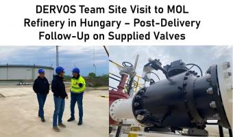
1. Project Background and Purpose of the Visit Previously, DERVOS supplied a batch of floating ball valves, trunnion-mounted ball valves, and swing check valves for the MOL refinery upgrade project in Hungary. Detailed specifications and technical data for this project are available in the previous case study. Recently, the DERVOS team visited Hungary to conduct a follow-up inspection at the same project site. The purpose of the visit was to evaluate the actual operating condition of the supplied valves, communicate directly with the client’s on-site engineering team, and collect feedback after several months of operation. 2. Current Project Status During the visit, it was confirmed that the MOL refinery is currently in a post-incident recovery phase. In October 2025, a fire occurred in the AV3 crude distillation unit, and repair work is ongoing. Full production capacity is expected to resume in Q3 2026. Despite this, in units that remain operational or are in maintenance intervals, all valves supplied by DERVOS are functioning normally. The client confirmed that no performance issues related to DERVOS valves have been reported. 3. Site Inspection Details The DERVOS team accessed the valve installation areas for on-site inspection. Particular attention was given to four trunnion-mounted ball valves equipped with 2-meter extended stems, a customized design to meet specific operating distance requirements. It was observed that the extended stem design allows operators to control the valves from a safe and accessible distance. The IP68-rated worm gear operators also demonstrated reliable sealing performance under local environmental conditions. The team also inspected floating ball valves and swing check valves installed in medium-pressure and high-temperature zones. No leakage or abnormal operation was identified. 4. Client Feedback During technical discussions, the client’s engineering team provided positive feedback. One project manager commented: “DERVOS clearly understands our operating conditions. The extended stem solution is exactly what we required. So far, the valves have operated reliably, with no unplanned downtime.” The client also acknowledged DERVOS for its prompt response during the delivery phase and the clarity of the technical documentation provided. 5. After-Sales Service Actions This visit was part of DERVOS’s standard after-sales follow-up. For each project, DERVOS provides an 18-month warranty from the date of shipment. Any quality-related issues are addressed promptly. During the visit, the team reviewed installation and maintenance records together with the client’s on-site maintenance personnel. No outstanding issues were identified. 6. Additional Project Context The MOL Danube Refinery, located in Százhalombatta south of Budapest, is one of the largest refineries in Central and Eastern Europe, with a processing capacity of 165,000 barrels per day. MOL Group is also advancing geothermal exploration around the refinery and has established a solar park and a green hydrogen facility. Although DERVOS valves are used in a conventional refinery upgrade project, this visit provided broader insight into the client’s transition toward low-carbon operations. 7. Conclusion and Outlook This site visit in Hungary was more than a routine follow-up. It reflects DERVOS’s commitment to the full product lifecycle—from engineering and delivery to post-commissioning support. Going forward, DERVOS will continue to provide reliable valve solutions and proactive field support for MOL and other refinery clients across Europe.
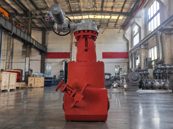
This application case focuses on a 14" 4500LB F91 Pressure Seal Gate Valve used in a high-temperature boiler project in Spain, where the valve must withstand severe pressure, elevated temperature, and reliable shut-off requirements. As one of the critical Power Plant Valves used for boiler and main steam isolation, the supplied valve adopts a pressure seal bonnet, parallel double disc structure, rising stem, full-bore design, BW ends, and electric actuation. The key selection purpose was to provide stable isolation for a high-pressure and high-temperature boiler pipeline. With ASTM A182 F91 Type 2 high-temperature material and a bypass valve for pressure equalization, the valve is designed to support safer operation during opening and closing under demanding service conditions. Project Background: High-Temperature Boiler Valve Application in Spain The Spanish project required a gate valve for high-temperature boiler service. According to the available project information, the operating condition involved high pressure and high temperature, with a 4500LB pressure class and a design temperature of 649°C.Selecting a High Pressure Valve and High Temperature Valve for this operating condition requires careful consideration of pressure class, material strength, creep resistance, sealing design, and thermal stability. For this type of service, ordinary carbon steel valves or low-pressure gate valves cannot provide sufficient material strength, thermal stability, or sealing reliability. A pressure seal gate valve was selected because its bonnet sealing performance becomes more effective as internal pressure increases. This makes the structure suitable for severe high-pressure steam and boiler pipeline applications. Challenges in High-Pressure and High-Temperature Boiler Service 1) Severe pressure and temperature: The valve is designed for Class 4500 service, with a design pressure of 184.40 bar and design temperature of 649°C. The material must maintain strength and creep resistance at elevated temperature. 2) Reliable shut-off requirement: Boiler isolation valves must provide stable sealing performance during start-up, shutdown, and operating transitions. Leakage or unstable disc seating may affect system safety and maintenance planning. 3) Operation under high differential pressure: Large high-pressure gate valves can be difficult to operate when pressure is not balanced across the disc. A bypass valve is therefore used for pressure equalization before main valve operation. 4) Welded-end pipeline connection: BW ends are suitable for severe service pipelines where flange leakage risk needs to be reduced. The project required connection according to ASME B16.25, with SMLS pipe wall thickness MW 46 mm. DERVOS Solution: F91 Pressure Seal Parallel Double Disc Gate Valve To meet these requirements, DERVOS Valve supplied a 14" Class 4500 pressure seal gate valve manufactured from ASTM A182 F91 Type 2 material.For severe boiler and power-generation service, Forged Steel Valves manufactured from high-temperature alloy grades such as F91 are commonly considered where pressure-containing strength and creep resistance are critical. F91 is a chromium-molybdenum high-temperature alloy steel commonly selected for boiler, power generation, and high-temperature steam systems because of its high-temperature strength and creep resistance. The valve adopts a parallel double disc design with full-bore flow passage. Compared with a conventional wedge gate design, the parallel double disc structure can help achieve stable seating performance in high-pressure service. The pressure seal bonnet improves bonnet sealing reliability as line pressure increases, making the structure suitable for high-pressure boiler isolation. An AOX electric actuator was selected for controlled operation. In addition, the valve is equipped with a bypass valve, allowing pressure equalization before the main valve is opened or closed. This reduces operating load and supports safer operation in high-pressure service. Key Technical Specifications of the 14" 4500LB Gate Valve Valve Type Pressure Seal Gate Valve Structure Parallel Double Disc, Rising Stem, Full Bore Size 14" / DN350 Pressure Rating Class 4500 / 4500LB Body / Bonnet Material ASTM A182 F91 Type 2 Disc / Seat F91 + STL Stem F6A 2 + N Trim Trim #5 Connection BW, ASME B16.25 Pipe Wall Thickness SMLS MW 46 mm Operation AOX Electric Actuator Design Standard ASME B16.34 Test & Inspection API 598 Design Pressure 184.40 bar Design Temperature 649°C Shell Test Pressure 116.4 MPa Seat Test Pressure 47.4 MPa Additional Feature Bypass valve for pressure equalization Why F91 Material Was Selected for Boiler Service The main material of the valve is ASTM A182 F91 Type 2. For high-temperature boiler and steam pipeline applications, F91 material provides better high-temperature strength than ordinary carbon steel. Th...
Copyright © 2015-2026 DERVOS VALVE CO.,LTD.All Rights Reserved Blog / Sitemap / XML / Privacy Policy