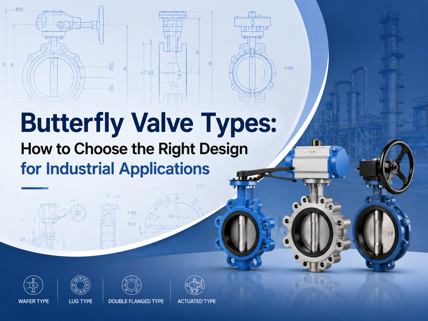
The main butterfly valve types include concentric, double offset, triple offset, wafer, lug, flanged, soft-seated, metal-seated, manual, pneumatic, and electric butterfly valves. The right choice depends on pressure, temperature, media, leakage requirement, installation space, and operation frequency. What Are the Main Butterfly Valve Types? Butterfly valves are usually classified by disc design, body connection, seat material, and actuation method. This classification is important because two valves may both be called butterfly valves, but their service limits can be very different. A butterfly valve uses a rotating disc to isolate or regulate flow. Because of its compact structure, light weight, and quarter-turn operation, it is widely used in water treatment, power plants, chemical processing, HVAC, marine systems, and general industrial pipelines. For buyers, the key question is not simply “which type is cheaper?” It is “which type can handle the actual pressure, temperature, media, and sealing requirement?” Concentric Butterfly Valve A concentric butterfly valve has the stem located on the centerline of the valve body and disc. It is also called a centerline butterfly valve. This type is commonly used for low-pressure and general-service applications, especially with water, air, and non-aggressive fluids. It is simple, economical, and easy to maintain. The limitation is seat wear. During opening and closing, the disc stays in contact with the soft seat for much of its movement. For higher pressure, higher temperature, or stricter shutoff requirements, double offset or triple offset designs are often more suitable. Double Offset Butterfly Valve A double offset butterfly valve uses two offsets to reduce friction between the disc and seat. This improves sealing performance and helps extend service life compared with a basic concentric design. Double offset butterfly valves are often selected for medium-pressure industrial service, including oil and gas, water supply, power generation, and chemical systems. They are useful when the application needs better durability but does not require a full metal-seated triple offset design. This type is also commonly called a high-performance butterfly valve. Before selection, buyers should confirm the pressure class, seat material, shaft sealing design, and expected operation frequency. Triple Offset Butterfly Valve A triple offset butterfly valve adds a third geometric offset to create a more advanced sealing structure. It is typically used for high-temperature, high-pressure, or severe-service applications. The design reduces rubbing between the sealing surfaces during operation. Many triple offset butterfly valves use metal seats, making them suitable for steam, oil and gas, chemical, and other demanding media. For these applications, standards and testing matter. Buyers often need t...
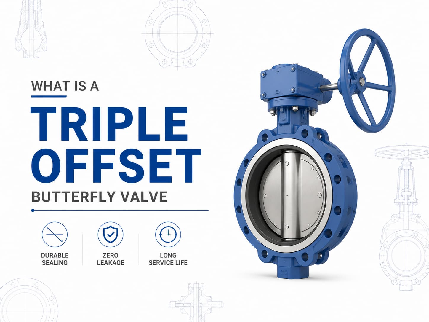
A triple offset butterfly valve is a high-performance isolation valve designed for applications where conventional resilient-seated or double offset butterfly valves cannot meet pressure, temperature, or leakage requirements. By using a three-offset sealing design, the valve achieves a metal-to-metal sealing mechanism with reduced friction between the disc and seat during operation, making it suitable for demanding services such as oil and gas, petrochemical, power generation, LNG, steam, and industrial process systems. Triple Offset Butterfly Valve Design and Working Principle Unlike a concentric butterfly valve, where the shaft is positioned at the centerline of the disc and seat, a triple offset butterfly valve incorporates three independent geometric offsets. The first offset moves the shaft away from the centerline of the valve body, the second offset shifts the shaft from the pipeline centerline, and the third offset introduces a conical sealing surface instead of a circular sealing profile. This geometry allows the disc to move away from the seat immediately after rotation begins, eliminating rubbing between sealing surfaces. The main advantage of this design is that the sealing force is generated by torque rather than continuous compression of soft materials. If the application requires high-temperature service, then a metal-seated triple offset butterfly valve is often preferred because elastomer seats may degrade under elevated temperatures. If the medium contains abrasive particles or aggressive chemicals, then material selection for the disc, seat, and body becomes critical to prevent erosion, corrosion, and leakage during long-term operation. Triple Offset Butterfly Valve Standards and Materials A triple offset butterfly valve is commonly manufactured according to standards such as API 609, EN 593, and ISO 5752, with pressure ratings ranging from Class 150 to Class 600 and higher depending on design requirements. Typical materials include carbon steel, stainless steel, duplex stainless steel, aluminum bronze, and nickel-based alloys. For corrosive seawater applications, aluminum bronze alloys such as C95500 or C95800 may be selected, while sour service applications may require materials compliant with NACE MR0175/ISO 15156 requirements. Triple Offset Butterfly Valve Sealing Performance and Leakage Control The sealing performance of a triple offset butterfly valve depends on the interaction between the sealing ring, seat surface finish, operating torque, and material compatibility. Since the sealing surfaces contact only at the final closing position, mechanical wear is significantly reduced compared with traditional butterfly valve designs. If zero leakage is required for critical isolation, then the valve design, pressure class, and applicable leakage standard, such as API 598 or ISO 5208, must be considered during specification. Triple Offset Butterfly Valve Applications and S...
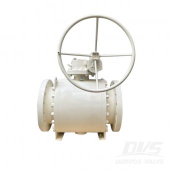
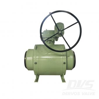
Ball valves and plug valves are both quarter-turn rotary valves used for on-off control and isolation in industrial piping systems. Although they share similar operating principles, their internal designs result in different performance characteristics, especially in terms of sealing, pressure capability, operating torque, maintenance requirements, and suitability for different media. The selection between a ball valve and a plug valve should be based on actual operating conditions rather than valve type preference. If the application requires tight shutoff, frequent operation, and low operating torque, then a ball valve is often preferred. If the system involves dirty media, abrasive particles, or large flow passages, then a plug valve may provide better reliability. Design Differences and Sealing Performance A ball valve uses a spherical closure element with a drilled bore. When the valve is open, the bore aligns with the pipeline to provide a nearly unrestricted flow path. When rotated 90 degrees, the solid section of the ball blocks the passage and provides shutoff. A plug valve uses a cylindrical or conical plug with a flow passage through the center. The plug rotates inside the body to control flow. Depending on the design, plug valves can be lubricated, sleeved, or non-lubricated, with each structure offering different sealing characteristics. The sealing mechanism is one of the main differences between the two valves. Ball valves generally use soft seats, metal seats, or a combination of both to achieve reliable shutoff. If the system requires bubble-tight isolation, especially in gas service or critical process applications, then a properly selected ball valve can provide excellent sealing performance. Plug valves rely on the contact between the plug and the valve body or sleeve. Lubricated plug valves use sealant injected between the plug and body to reduce friction and improve sealing. This design can perform well in applications where the media contains contaminants because the sealant helps protect the sealing surfaces. Application Considerations Operating conditions determine whether a ball valve or plug valve is more suitable. Ball valves are widely used in oil and gas, petrochemical, LNG, chemical processing, and power industries where reliable shutoff is required. Floating ball valves are commonly applied in lower pressure systems, while trunnion mounted ball valves are preferred for larger sizes and higher pressure ratings because the trunnion support reduces operating torque. If the valve will experience frequent cycling, then a ball valve usually provides an advantage due to its low friction operation and quarter-turn actuation. However, careful consideration is required when handling fluids containing solid particles. If abrasive particles become trapped between the ball and seat, then seat damage and leakage may occur. Plug valves are often s...
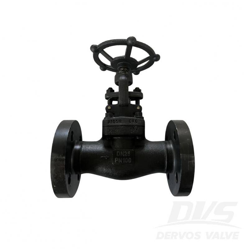
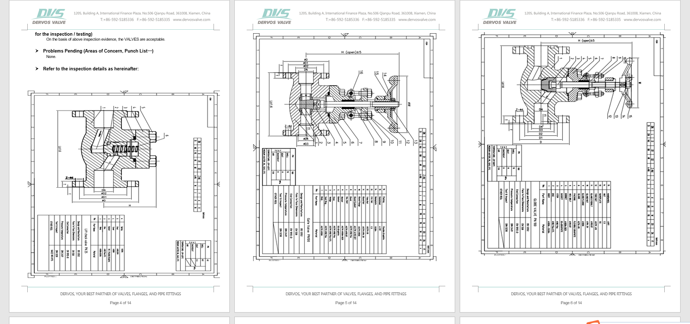
DN25 PN100 globe valve is made according to API 602 standard. The valve body is made of A105N+SS304. It has the structural characteristics of bolt cover, straight through type. Its connection mode is EN1092-1 D. And it has hand wheel operation mode.
Payment:
30% when order confirmed, 70% before shipmentProduct Origin:
ChinaColor:
CustomizationShipping Port:
Shanghai, ChinaLead Time:
30~60 days Ex Works after order confirmationMaterial:
A105N+SS304Method of Operation:
Hand WheelProduct Description
|
Type |
Globe Valve |
|
Size |
DN25 |
|
Pressure |
PN100 |
|
Connection |
EN1092-1 D |
|
Operation |
Hand Wheel |
|
Body Material |
A105N+SS304 |
|
Design Norm |
API 602 |
|
Face to Face Dimensions |
EN 558 |
|
End Connection |
EN 1092-D |
|
Pressure-temperature |
DIN 2401 |
|
Test & Inspection Code |
DIN 3230 |
|
Temperature |
-29 ~ 500°C |
|
Applicable Medium |
Water, Oil and Gas |
Features
1. Multiple connection methods such as flange connection and clamp connection can be used to meet the needs of different pipeline systems;
2. It has good corrosion resistance and can work stably in corrosive media for a long time, suitable for industries such as chemical, petroleum, and natural gas.
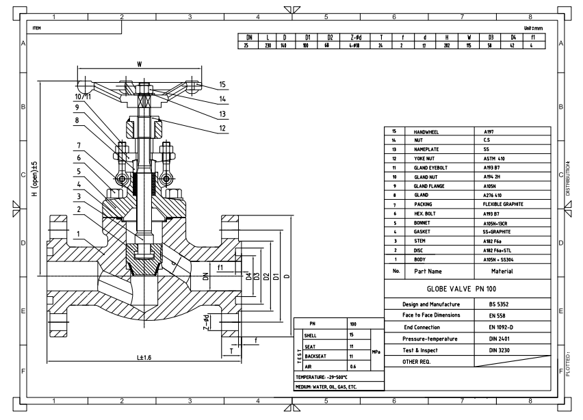
Technical Drawing
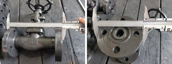
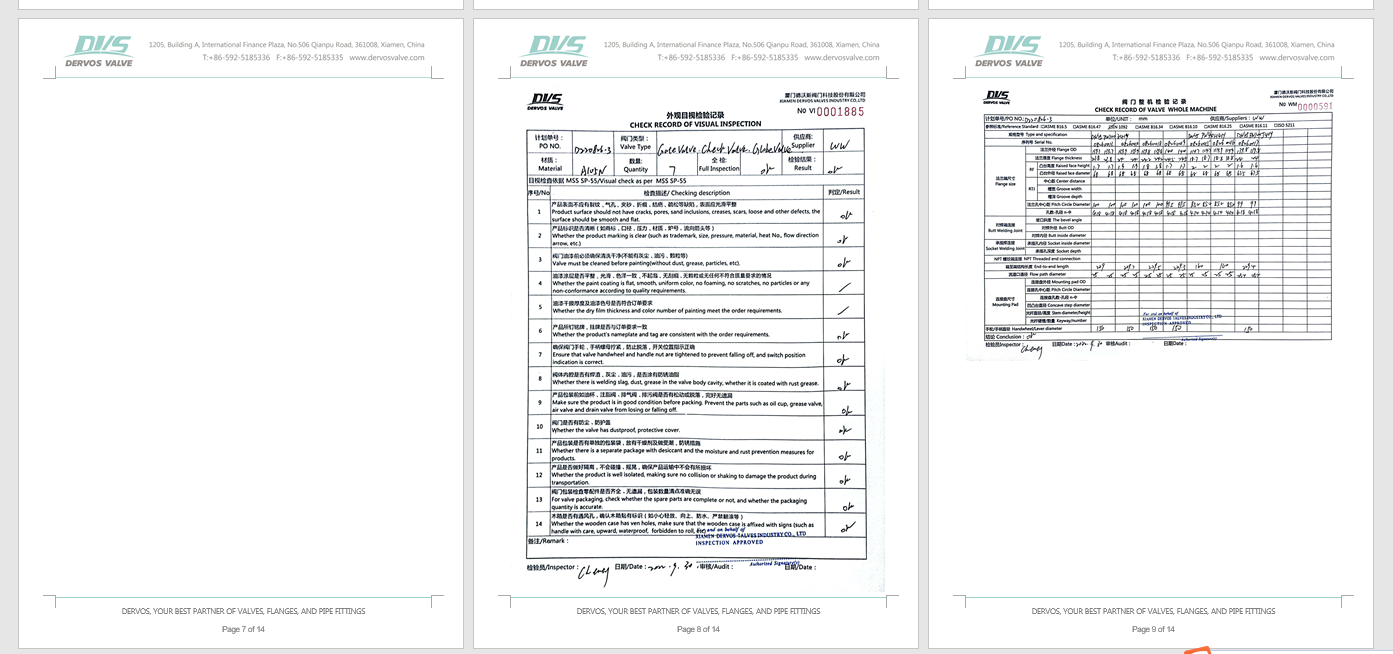
Dimension Checking
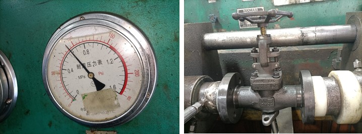
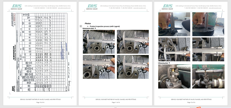
Pressure Testing
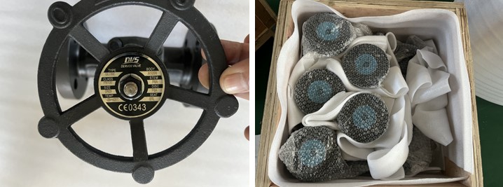
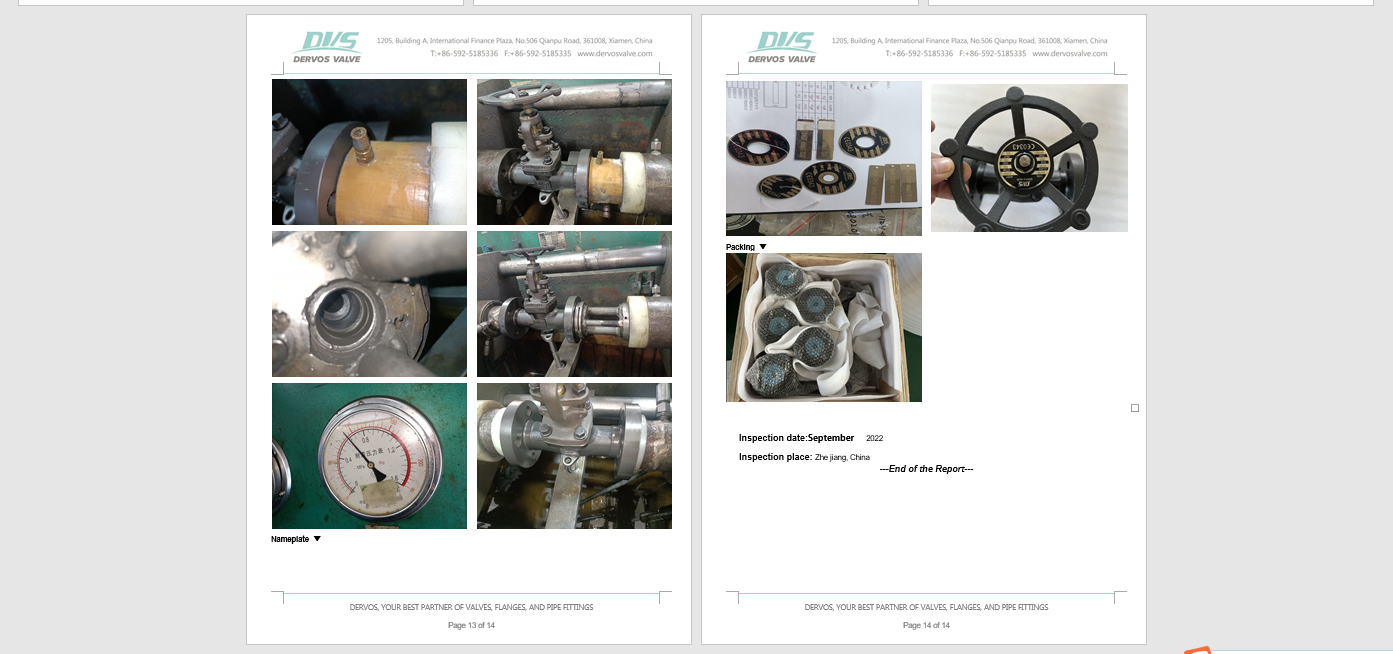
Nameplate & Packing
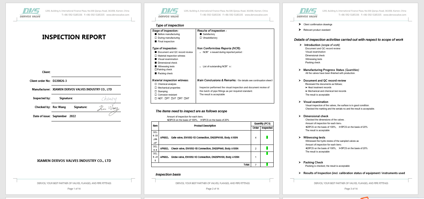
Inspection report
If you are interested in our products and want to know more details,please leave a message here,we will reply you as soon as we can.

The 1 inch 800LB female threaded globe valve has plug disc, reduced port and manual handwheel operation. The valve is made of A105N body and trim 5 as per API 602. Quick Detail Type Globe Valve Size 1'' Pressure Class 800 Construction Bolted Bonnet, Reduced Port, Outside Scew & Yoke ConnectionType NPT Female Thread OperationType Handwheel Operated Design Code API 602 End to End Dimension ASME B16.10 Connection ASME B1.20.1 Pressure & Temp ASME B16.34 Test & Inspection API 598 Body Material Forged Steel A105 TrimMaterial 13CR+Stellite Temperature Range -29℃~+427℃ Application Water, Oil, Gas Origin China Product Range 1.Size up to 4 inch 2.Design pressure between 150LB to 2500LB 3.Connection: flange, socket weld, thread 4.Operation: handwheel, gearbox, bare stem, with actuators 5.Body material: carbon steel, stainless steel, alloy steel 6.Trim material: trim 1, 5, 8, 10, 12, 16 and ect. 7.Bolted bonnet, pressure sealed bonnet, welded bonnet, screwed bonnet 8.Reduced bore, full bore Inspection Reports Along with each order, Dervos will provide inspection reports and material test reports free of charge after shipment. All these certificates will let you have a clear picture of inspection process and results. Plus, these reports can be used for traceability.
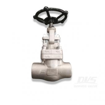
Globe valve with a non-return design, preventing reverse flow when in the open position, also suitable for isolation duty. Manually operated, supplied with a handwheel.
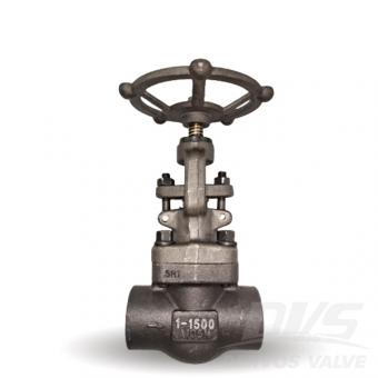
Quick Detail Type Globe Valve DN DN50 PN PN250 Construction Tee Pattern; Bolt Bonnet; Connection Type NPT Operation Type Handwheel Design Code API602 Screw End ASME/ANSI B1.20.1 Test & Inspection API598 Body Material A105+STL Trim Material A276-420 Medium Water, Oil and Gas Origin China Features -- Globe valves have both good throttling and shutoff capabilities -- Easy to maintain and resurface the seats -- Can be used as a stop-check valve if the disc is not attached to the stem Technical Drawing Dimension Check Witnessing Tests Dervos Packaging Good packing means good first impression. Just imagine how do you feel differently when seeing two boxes below? And you will know the reason why in Dervos we value packaging so much. In Dervos, we make sure- Every valve is clean and dry. -Clean the valve before packing -Add anti-rust oil -Add flange cover No damage to valves in delivery. -Fix the valve with iron wire -Separate the valve with soft material -Layer the valve with plywood -Strong box and clear shipping mark
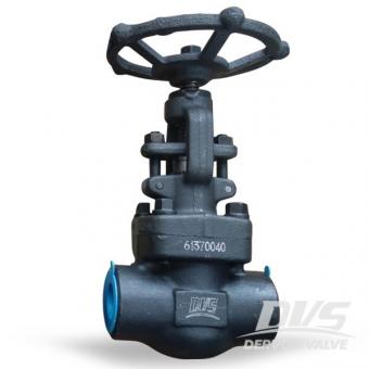
With outside screw and yoke, handwheel operation, NPT, the forged steel globe valve is made of A105 and designed as per BS5352.
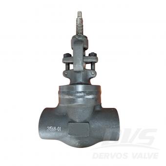
11/2" 800LB globe valve is made according to API602 standard. The valve body is made of A105+STL. It has the structural characteristics of welded bonnet. Its connection mode is SW. And it has hand wheel operation mode.
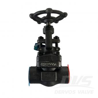
3/4" 800LB globe valve is made according to API 602 standard. The valve body is made of A105N+ STL. It has the structural characteristics of plug, disc swivel plug, body seat and OS&Y. Its connection mode is SW+FNPT. And it has hand wheel operation mode.
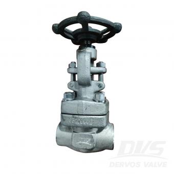
1/2" 800LB globe valve is made according to API 602 standard. The valve body is made of ASTM A182 F316/F316L+STL. It has the structural characteristics of bolt cover, disc swivel plug, body seat and OS&Y. Its connection mode is SW. And it has hand wheel operation mode.
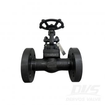
DN25 PN63 globe valve is made according to BS5352 standard. The valve body is made of A105N+SS304. It has the structural characteristics of bolt cover, straight through type. Its connection mode is EN1092-1 D. And it has hand wheel operation mode.
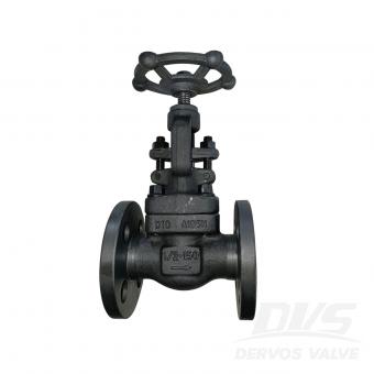
1/2" 150LB globe valve is made according to API 602 standard. The valve body is made of ASTM A105N+STL. It has the structural characteristics of pass-through type. Its connection mode is RF. And it has hand wheel operation mode.

1/2" 150LB globe valve is made according to API 602 standard. The valve body is made of ASTM A105N+STL. It has the structural characteristics of pass-through type. Its connection mode is RF. And it has hand wheel operation mode.

1" 600LB globe valve is made according to API 602 standard. The valve body is made of ASTM A105N+STL. It has the structural characteristics of bolt cover, straight through type. Its connection mode is RF. And it has hand wheel operation mode.

DN25 PN40 forged steel globe valve is made according to BS 5352 standard. The valve body is made of A182-F316+STL. It has the structural characteristics of bolt cover and straight through type. Its connection mode is EN1092-1 B. And it has hand wheel operation mode.
Copyright © 2015-2026 DERVOS VALVE CO.,LTD.All Rights Reserved Blog / Sitemap / XML / Privacy Policy