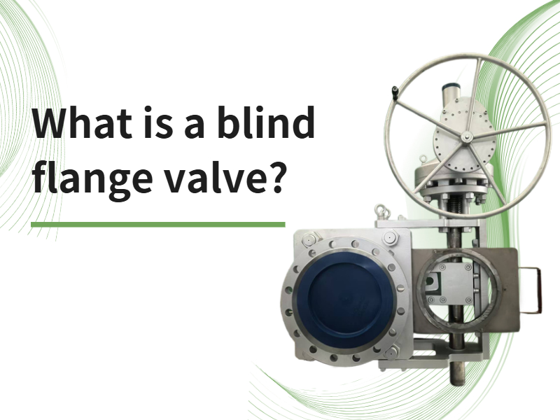
In industrial valve systems, a high-quality blind plate valve ensures safe and efficient operation of equipment. It is suitable for gas pipelines in metallurgy, chemical processing, petroleum, and municipal systems, serving as an effective device for positive gas isolation. Working Principle and Features The blind plate valve consists of left, center, and right valve bodies, a valve plate, shafts, a compensator, and two drive units (for clamping and travel respectively). The clamping mechanism uses a drive assembly to actuate a linkage system, enabling three lead screws to operate synchronously and press the valve bodies against the valve plate to achieve sealing. This design provides good synchronization and uniform sealing force distribution. Positioning rollers are installed along the outer lower edge of the valve plate to enhance sealing reliability and ensure overall stability and sealing accuracy during operation, thereby extending the service life of the valve. Valve Operating Sequence The clamping drive unit actuates the crank and linkage mechanism, causing the lead screws to rotate synchronously and retract the center body from the sealing surfaces (release condition). Guide wheels installed on the center body move laterally and simultaneously drive the valve plate. When the valve bodies are fully opened, the valve plate is positioned between the sealing faces of the left and right bodies, and the sealing surfaces are completely disengaged. The plate drive unit is then activated. Through a lever arm mechanism, the valve plate rotates, bringing the blind plate into the pipeline position. The clamping drive unit is started again to fully clamp the valve plate, completing valve closure. Valve Opening The clamping drive unit first fully releases the valve bodies. The turning drive unit then rotates the valve plate so that the through-port aligns with the pipeline. Finally, the clamping electric actuator presses the valve plate to complete the opening operation.
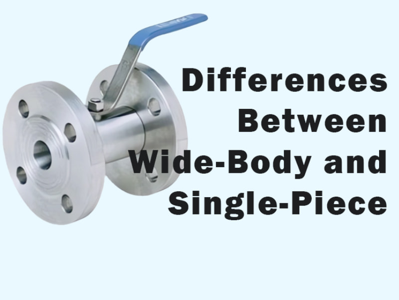
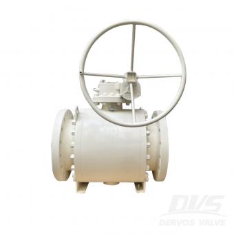
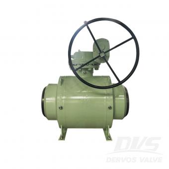
Wide-body ball valves and single-piece ball valves are both types of ball valves used for controlling the on/off flow of medium in pipelines. Both wide-body and single-piece ball valves feature a one-piece (integral) body design, unlike split-body designs. This differs from two-piece and three-piece ball valves, which have segmented valve bodies. For internally threaded wide-body ball valves, the valve body is made from round or hexagonal stock, using either bar material or forged components. The ball core features a reduced-diameter design and is inserted from one side of the valve body. The stem uses an internal anti-blowout structure. Flat surfaces are machined on both the inlet and outlet sides of the body to facilitate assembly of the ball valve and allow the use of wrenches during pipeline installation. In wide-body ball valves, the stem stuffing box is relatively shallow, and the internal packing volume is limited, resulting in a moderate sealing performance of the stem. Therefore, these valves are more suitable for low-pressure medium applications. In contrast, two-piece and three-piece ball valves feature stem stuffing box structures that provide reliable sealing for high-pressure medium applications. The structure of flanged wide-body ball valves is essentially the same as that of internally threaded wide-body ball valves. Typically, the flange is connected to the intermediate valve body via threaded fasteners, although some designs utilize a forged one-piece structure. Externally threaded wide-body ball valves can use a union-type structure, where the union is directly welded to the pipeline and connects to the external threads on the valve body. This design allows for easy disassembly and reassembly during valve maintenance or replacement without requiring separate unions on the pipeline. The valve bodies of single-piece internally threaded ball valves and single-piece flanged ball valves are manufactured using casting processes, with the ball core featuring a reduced-diameter design. The stem uses an internal anti-blowout structure. The inlet and outlet ends of single-piece internally threaded ball valves have a hexagonal shape, similar to conventional internally threaded valves, to facilitate wrench operation and secure installation. In single-piece flanged ball valves, the flange and valve body are cast as a single unit, eliminating the need to machine and assemble the flange separately as in wide-body flanged ball valves. This approach reduces cost and simplifies the manufacturing process. Single-piece wafer-style ball valves have a shorter valve body length, making them more suitable for pipelines with limited space. Wide-body and single-piece ball valves both use a reduced-diameter ball design, resulting in higher flow resistance compared with two-piece and three-piece ball valves. The main differences are as follows: Valve Body Manufacturing Process ● Wide-bo...
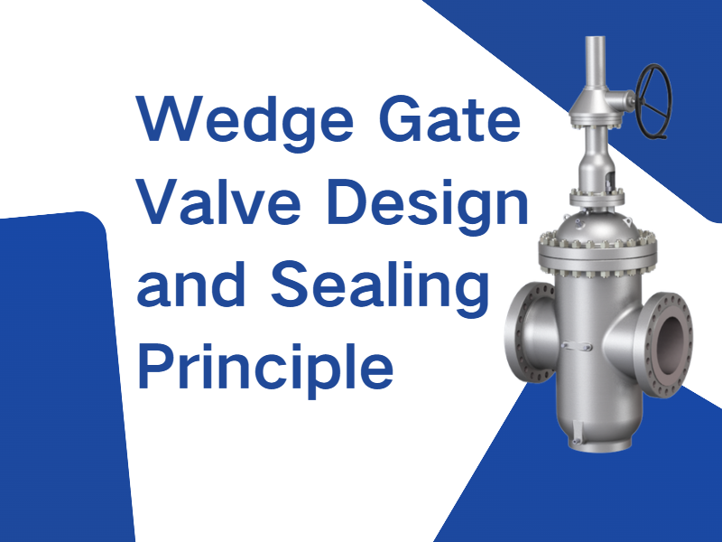
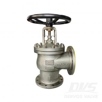
In a wedge gate valve, the gate sealing surfaces are wedge-shaped, forming a specific angle relative to the gate centerline. The gate is driven downward by the valve stem to achieve closure. As the stem thrust increases, the normal force acting on the wedge-shaped sealing surfaces also increases, creating a forced sealing effect. This design significantly improves sealing performance under low-pressure conditions. During opening, the gate sealing surfaces disengage from the seat immediately, which helps reduce wear on the sealing faces and extends the service life of the valve. Applicable Standards for Wedge Gate Valves Wedge gate valves are commonly manufactured in accordance with the following standards: ● GB/T 12234-2019 – Steel gate valves with bolted bonnet for petroleum and natural gas industries ● GB/T 12232-2005 – General-purpose flanged cast iron gate valves ● API Standard 600 (2015) – Steel gate valves for petroleum and natural gas industries Types of Wedge Gate Valve Gates Wedge gate valves are typically available in three gate configurations:Solid wedge gate, Flexible wedge gate, Double wedge gate. The flexible wedge gate and double wedge gate rely on controlled deformation of the sealing surfaces to achieve improved contact with the valve seat. This design enhances sealing reliability and effectively prevents gate binding or jamming caused by temperature variations, ensuring smooth operation even under fluctuating thermal conditions. Parallel Slide Gate Valve Design and Sealing Principle In a parallel slide gate valve, the sealing surfaces at both the inlet and outlet ends of the gate are parallel to the gate centerline. For single-gate configurations, sealing is primarily achieved by the medium pushing a floating gate or floating seat into position. In double-gate configurations, sealing can be accomplished through springs or an expansion mechanism between the gates. Throughout the opening and closing process, the gate and seat sealing surfaces remain in constant contact, ensuring reliable sealing. Applicable Standards for Parallel Slide Gate Valves Common standards for parallel slide gate valves include: ● GB/T 23300-2009 – Parallel slide gate valves ● JB/T 5298-2016 – Steel parallel slide gate valves for pipelines ● API 6D – Pipeline valves for petroleum and natural gas industries Types and Features of Parallel Slide Gate Valves Parallel slide gate valves are available in single-gate and double-gate configurations. ● Gates may include flow-through holes or be solid. Gates with flow-through holes match the seat inner diameter, facilitating cleaning and drainage of the pipeline. ● Sealing can be configured at the inlet end, outlet end, or at both ends, depending on application requirements. This design ensures flexibility in sealing arrangements while maintaining reliable oper...

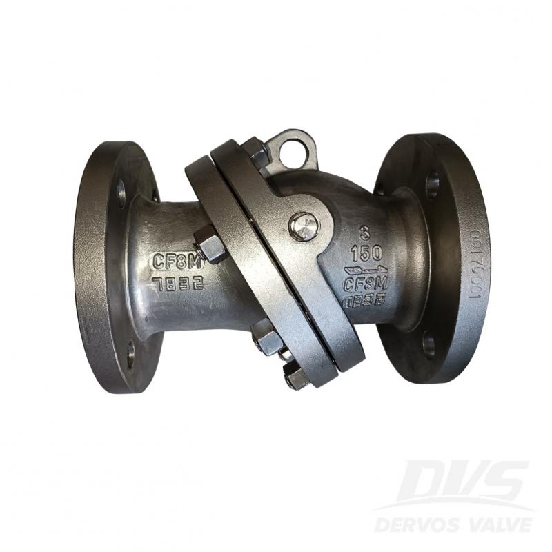
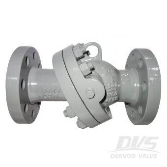
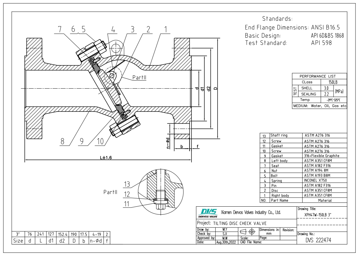
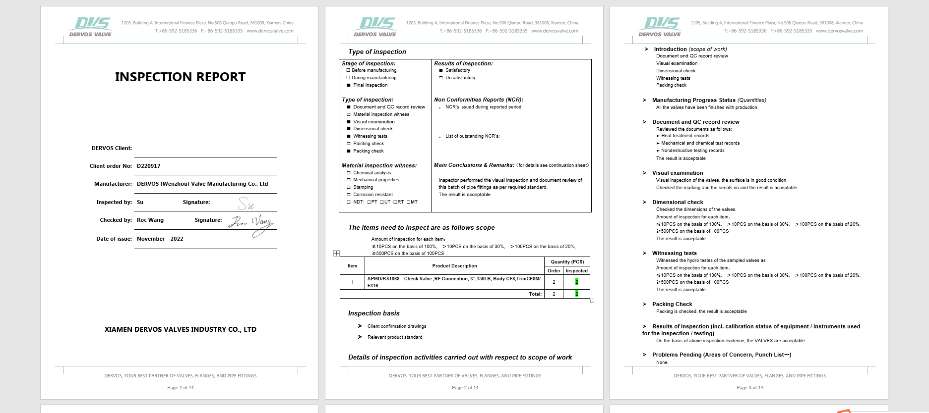
3" 150LB tilting disc check valve is made according to API 6D & BS1868 standard. The valve body is made of ASTM A351 CF8M. It has the structural characteristics of tilting disc type, bolt cover. Its connection mode is RF.
Payment:
30% when order confirmed, 70% before shipmentProduct Origin:
ChinaColor:
CustomizationShipping Port:
Shanghai, ChinaLead Time:
30~60 days Ex Works after order confirmationMaterial:
ASTM A351 CF8MProduct Description
|
Type |
Tilting Disc Check Valve |
|
Size |
3" |
|
Pressure |
150LB |
|
Connection |
RF |
|
Body Material |
ASTM A351 CF8M |
|
Design Norm |
API 6D & BS1868 |
|
End Flange Dimensions |
ANSI B16.5 |
|
Test & Inspection Code |
API 598 |
|
Temperature |
-29 ~ 325°C |
|
Applicable Medium |
Water, Oil and Gas |
Features
1. The tilting disc design reduces fluid resistance and pressure loss, making the medium flow smoother and improving system efficiency;
2. Due to the tilting design and gravity effect of the valve disc, it can quickly close, reducing the risk of medium backflow, effectively preventing water hammer phenomenon, and protecting pipelines and equipment.
Technical Drawing
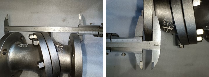
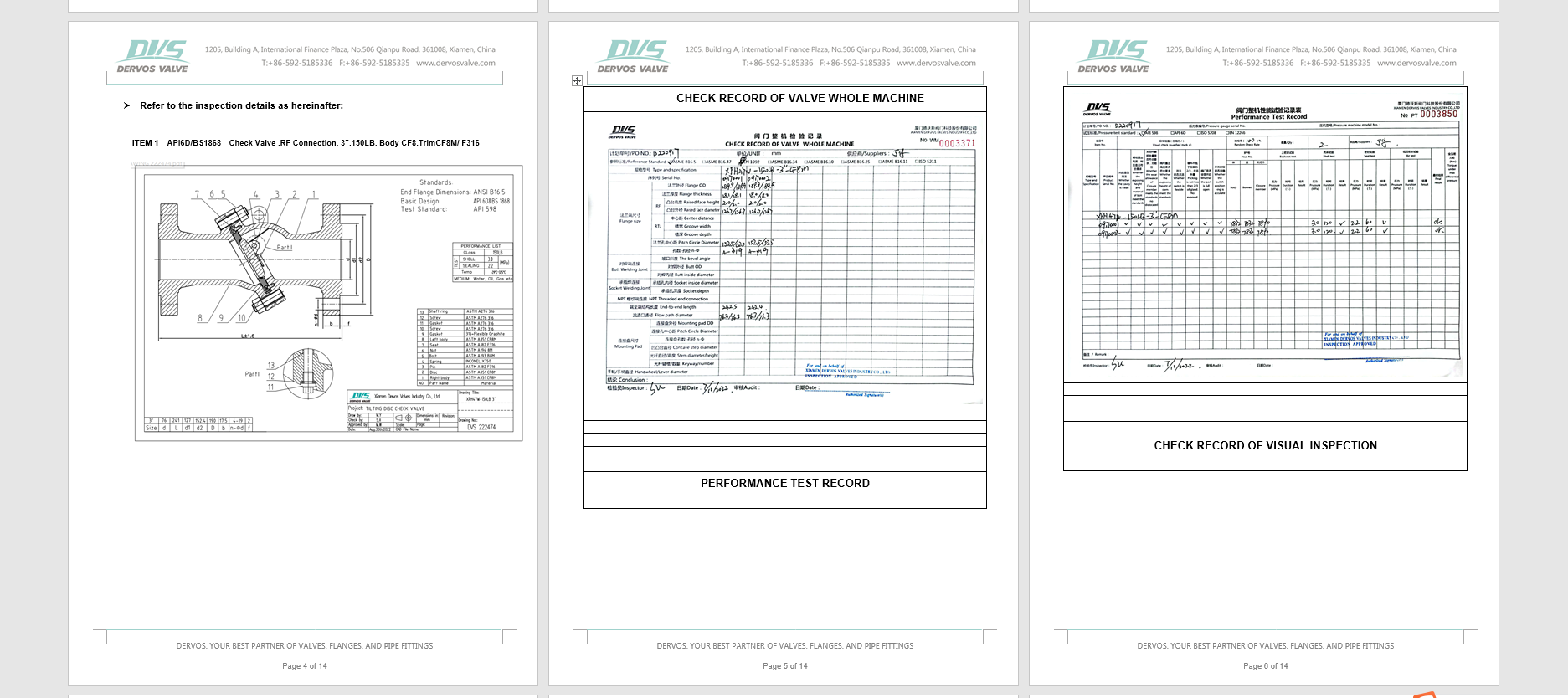
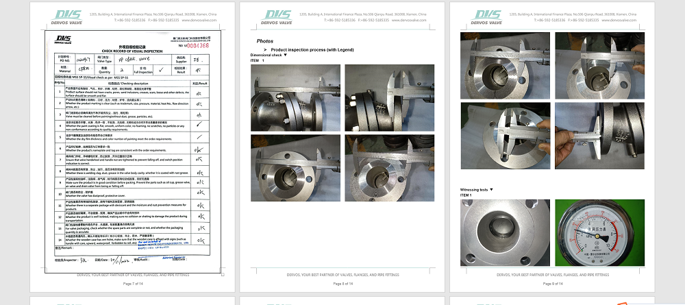
Dimension Checking
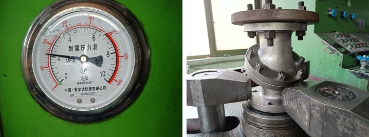
Pressure Testing
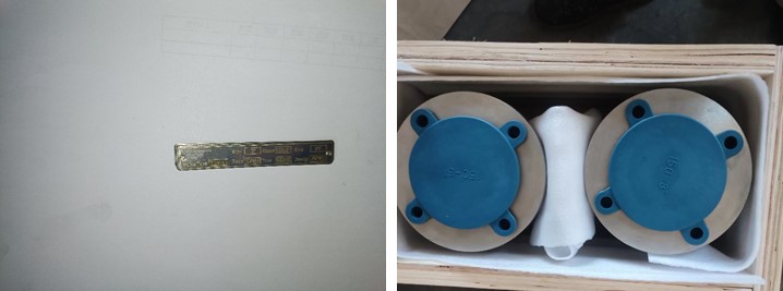
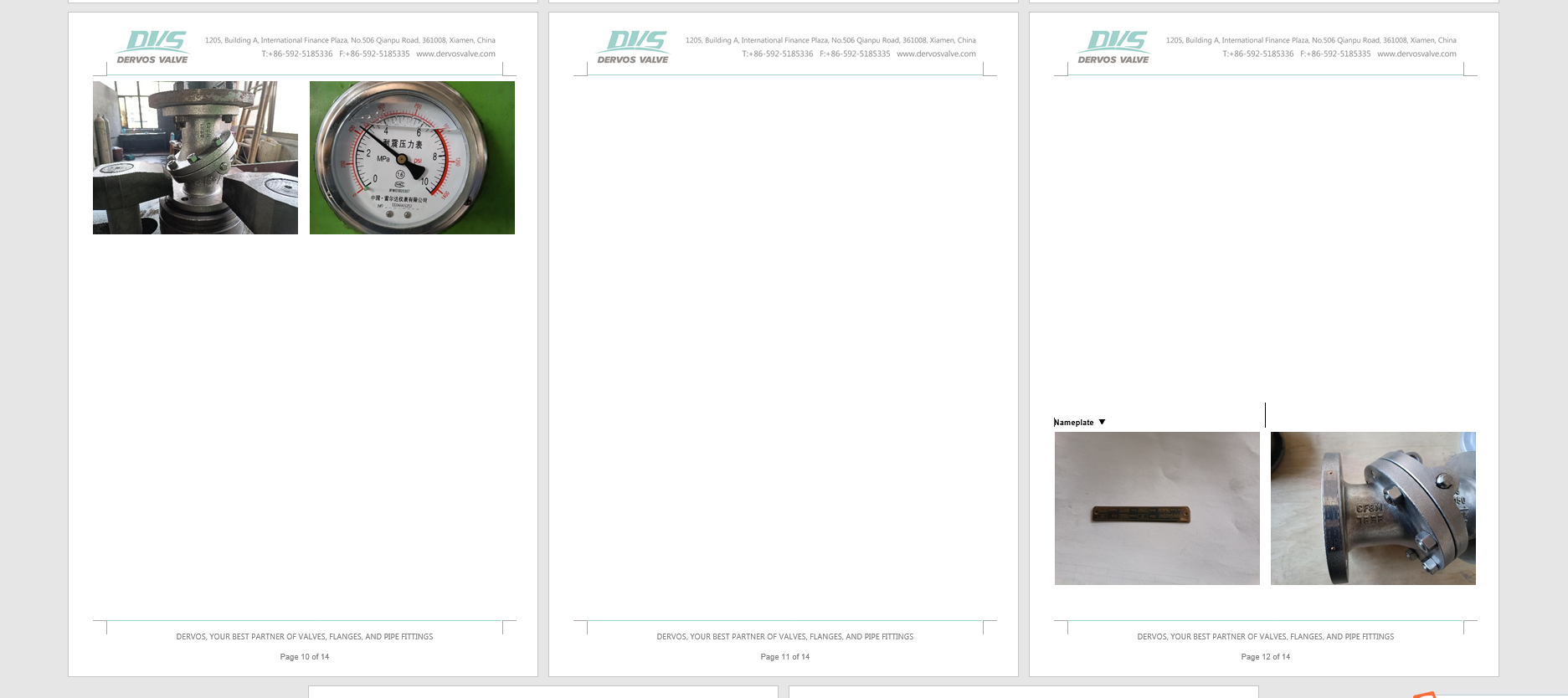
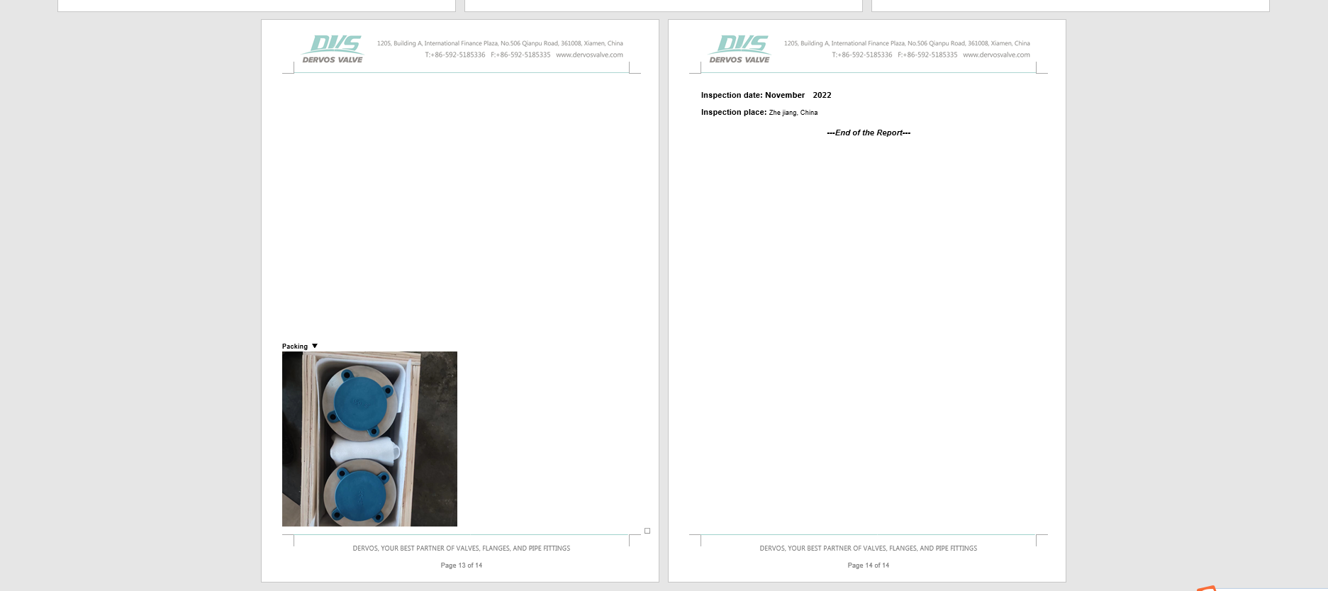
Nameplate & Packing
Inspection report
If you are interested in our products and want to know more details,please leave a message here,we will reply you as soon as we can.
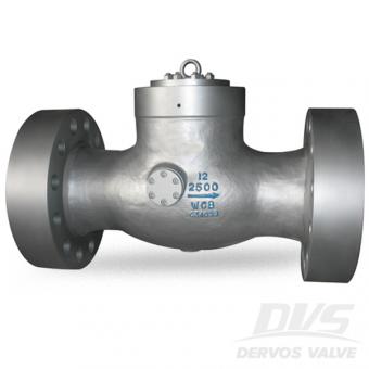
The 12 inch high pressure check valve is designed with pressure seal bonnet, RTJ flange, tilting disc, made of carbon steel WCB body and hard face sealing. Quick Detail Type Check Valve Size 12'' DesignPressure 2500LB Construction Pressure Seal Bonnet, Tilting Disc Type Connection RTJ Flange Design & Manufacture ASME B16.34 End to End ASME B16.10 Connection ASME B16.5 Pressure & Temp ASME B16.34 Test & Inspection API 598 Body Material A216 WCB Trim Material 13CR+STL Temp Range -29℃~+350℃ Media W.O.G. Product Range Body Material Range: WCB, WCC, WC1,CF8M, CF8, CF3, CF3M, LCB, LCC Size Range: 2”~60” (DN50~DN1500) End Connection Type: Flange End, Weld End Design Pressure Range: 150lbs~600lbs Temp Range: -46℃~ +425℃ Related Knowledge What is a tilting disc check valve? The disc of a tilting disc check valve has a pivot point at the center of it. It is desinged to overcome weaknesses of general type swing check valve. Compared to swing type check valve, the tilting check valve could remain fully open and steady at lower flow rates. That is to say, the swing check valve needs a high velocity of fluid to keep disc open and a higher cracking pressure. For low pressure situation, the pressure drop of a tilting disc check valve is much lower than the swing type. But at a higher flow rate, the tilting check valve has higher pressure drop than swing type.
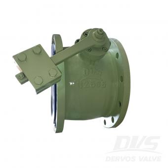
DN250 PN10 check valve body is made of A216 WCB+STL. It has the structural characteristics of heavy hammer on both sides and flange type. Its connection mode is RF.
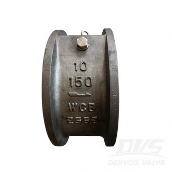
10" 150LB tilting disc check valve is made according to API 6D standard. The valve body is made of A216 WCB+SS316. It has the structural characteristics of swash plate type. Its connection mode is wafer.
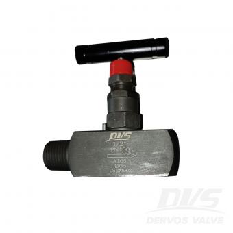
1/2" PN100 needle valve is made according to ASME B16.34 standard. The valve body is made of A105. It has the structural characteristics of straight-through. Its connection mode is Male/Female NPT. And it has lever operation mode.
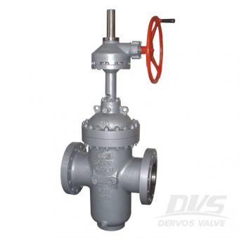
The API 6D through conduit gate valve is designed with 600 LB flange and gearbox connection. Made of carbon steel WCB, the 20 inch gate valve has soft seat design without diversion hole.
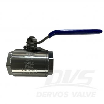
3/4” 150LB Forged Steel Floating Ball Valve is made according to API608 standard. The valve body is made of A182 F304. It has the structural characteristics of Full Bore, Floating Ball, Fire-safe and Anti-static, Blow-out Proof Stem. Its connection mode is NPT. And it has hand wheel operation mode. Product Parameters Type Forged Steel Floating Ball Valve Size 3/4” Pressure 150LB Connection NPT Operation H.W. Body Material A182 F304 Design Norm API 608 Face to Face MFG Screwed End ASME B1.20.1 Test & Inspection Code API 598 Temperature -29 ~ 120°C Applicable Medium Water, Oil and Gas Features 1.High-temperature F304 stainless steel body ensures superior corrosion resistance and durable performance. 2.API 608 certified design guarantees reliable shut-off and long-term service in demanding industrial application. Technical Drawing Dimension Checking Pressure Testing Nameplate & Packing Inspection Report
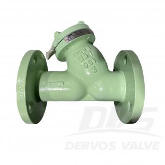
2" 150LB Y Strainer is made according to ASME B16.34 standard. The valve body is made of LCB. It has the structural characteristics of Y-Type, Double Mesh Screen, Mesh Size 1/16", Hole Pitch 3/32". Its connection mode is RF.
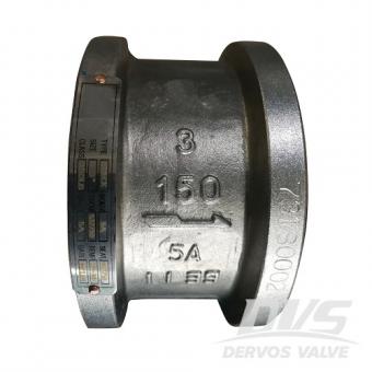
3" 150LB wafer check valve is made according to API594 standard. The valve body is made of A995 5A. It has the structural characteristics of built-in type and dual plate. Its connection mode is wafer type.

DN80 PN10 diaphragm valve is made according to BS 5156 standard. The valve body is made of WCB+ⅠⅠR. It has the structural characteristics of direct diaphragm valve G46. Its connection mode is RF. And it has hand wheel operation mode.

2" 600LB inverted pressure balanced lubricated plug valve is made according to API 6D standard. The valve body is made of A216 WCB. It has the structural characteristics of inverted pressure balance type, oil sealed. Its connection mode is RF. And it has Lever operation mode.
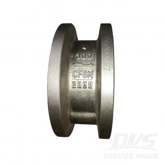
4" 300LB wafer check valve is made according to API 594 standard. The valve body is made of A351 CF8M. It has the structural characteristics of double disc and built in type. Its connection mode is wafer RF.
Copyright © 2015-2026 DERVOS VALVE CO.,LTD.All Rights Reserved Blog / Sitemap / XML / Privacy Policy