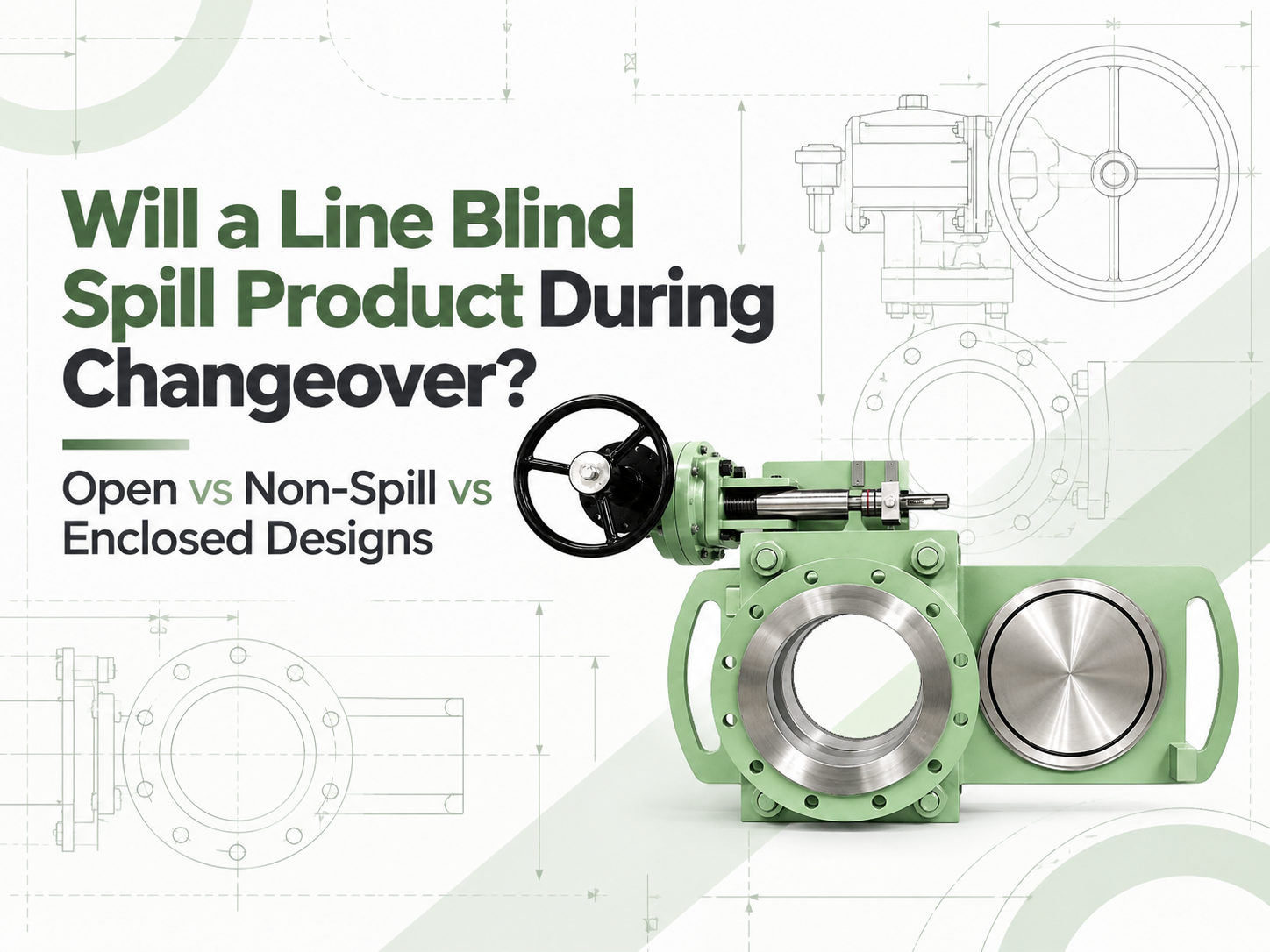
Yes, an open-body line blind can release residual product when it changes between the open and blind positions. A non-spill design does not make that residue disappear; it catches the liquid in a partial enclosure and directs it to a drain. An enclosed design can provide better control of liquid and vapour, but only when its housing, drain, vent and purge connections are engineered for the service. None of these labels should be read as permission to move the blind under live line pressure. Why Product Can Escape During Changeover When a line blind is fully clamped, its seals contain the process and the solid plate provides positive isolation in the blind position. Changeover is different. The sealing faces must separate before the spectacle or sliding plate can move. During that interval, the body cavity and plate path may be open to the surrounding area. The line should already be isolated, depressurised and drained, but “drained” rarely means perfectly dry. Liquid can remain as a film on the plate, collect in the lower body, or sit in a poorly drained pipe pocket. Gas service may leave flammable, toxic or odorous vapour. The amount released therefore depends as much on piping layout and the shutdown procedure as on the line blind itself. The Three Designs Manage Residue Differently Open-body design Residual liquid can drip from the exposed plate path into a temporary tray or the work area, while vapour disperses locally. This arrangement can suit water, steam condensate or other manageable media where easy access and visual inspection matter. It presents the highest potential for floor contamination and operator exposure. Non-spill design A bottom-and-side cover catches drips and sends them to a drain or recovery container; the top may remain open. This design is commonly considered for fuel terminals, marine service and liquid duties where ground or deck contamination must be controlled. It reduces dripping but may not contain vapour, and a blocked drain defeats its purpose. Enclosed design A housing surrounds more or all of the plate travel and may connect to a closed drain, purge, vent, flare or vapour-recovery system. It is better suited to toxic, flammable, odorous or environmentally sensitive service requiring controlled containment. The tradeoff is greater complexity in purging, inspection and maintenance, together with the need to manage trapped pressure deliberately. These names are not perfectly standardised across manufacturers. One supplier's “non-spill” model may be open at the top, while another product described as enclosed may use a more complete casing. The RFQ should show the enclosure arrangement and identify every opening rather than relying on the product name. Non-Spill Does Not Automatically Mean Zero Release For a liquid with low volatility, catching the remaining drops and routing them into a closed contai...
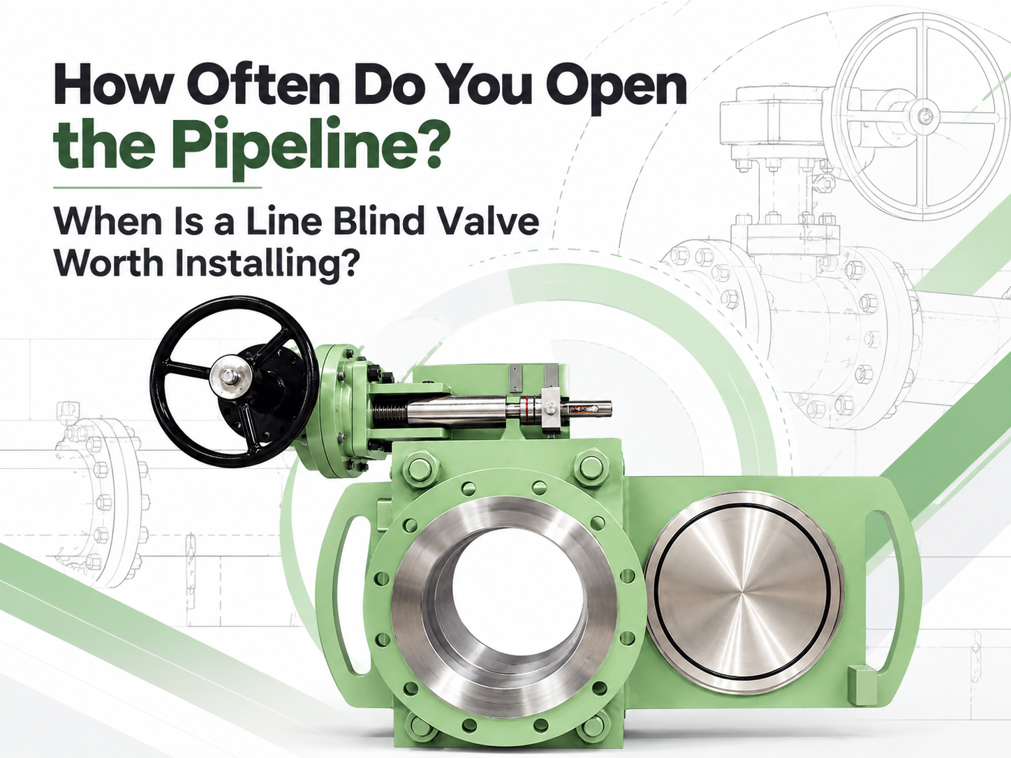
A line blind valve is worth evaluating when a pipeline is blinded several times a year, or when one conventional changeover causes hours of shutdown, lifting work or significant exposure to hazardous residue. No universal cycle count guarantees payback. A large critical line operated twice a year may justify the investment, while a small accessible line operated monthly may not. The decision should be based on the cost and risk of each complete isolation event, not frequency alone. There Is No Standard “Two Operations per Year” Rule Some suppliers use one or two annual changeovers as a screening threshold. That can start a discussion, but it is not an engineering rule. Frequency has very different consequences on a DN50 utility line and a DN600 process-gas main. For a preliminary review, the following bands are useful but not mandatory: Blinding frequency Initial interpretation Once per major turnaround or less A removable blind or spectacle blind is often more economical. One to three times per year Compare labor, lifting, outage duration and medium risk carefully. Quarterly to monthly A quick-action line blind is normally a strong candidate. Weekly or more often Purpose-built or automated isolation deserves detailed review; also confirm that a line blind is suitable for the required cycle duty. A low operating frequency can still support installation when every event requires scaffolding, a crane, several pipefitters or a long production interruption. Conversely, frequent operation does not justify a line blind if the process cannot accommodate its pressure, temperature, materials or maintenance needs. Count the Complete Changeover Traditional blinding is more than moving a plate. After the line is made safe, workers loosen bolting, spread the flange joint, handle the blind or spacer, replace gaskets, restore alignment, tighten the joint and complete leak checks. Large sizes add rigging and access equipment. A quick-action line blind keeps the spectacle or sliding plate supported inside the installed assembly. Manufacturer literature commonly reports one-person changeover in minutes rather than the man-hours needed for conventional flange work. Those figures are useful for screening, but the project calculation should use the plant’s own procedures and recorded shutdown times. Use a simple comparison: Annual avoided cost = operations per year x cost avoided per operation Avoided cost may include pipefitter hours, rigging, scaffolding, gaskets and bolting, leak testing and the production value of saved time. Keep categories separate to avoid double counting. Compare the annual saving with the line blind’s additional installed price and maintenance cost. Risk Can Matter More Than Simple Payback Repeated flange separation creates opportunities for residual-medium exposure, damaged flange faces, poor alignment and inconsistent bolt load...
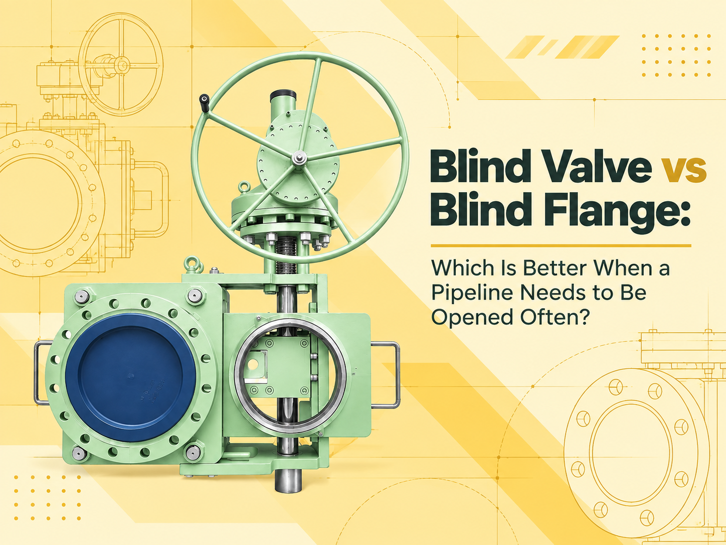
When a pipeline must be opened and positively isolated often, a line blind valve is usually the better choice. It keeps the blind mechanism permanently installed and lets operators change between open and blocked positions without repeatedly removing a bolted end closure. A blind flange costs less and has fewer moving parts, but it is better suited to closing a pipe end that will remain closed for long periods. This answer assumes that “blind flange” means a solid flange bolted to the end of a pipe or nozzle. A spectacle blind or a removable spade installed between two flanges is a different device, although it creates a similar solid-metal isolation barrier. Frequent Opening Changes the Cost Calculation The purchase price favors the blind flange. Its construction is simple, and maintenance is largely limited to checking the flange face, gasket, studs and nuts. If the closure will be disturbed only during an occasional turnaround, that simplicity is difficult to beat. Repeated opening changes the picture. Removing a blind flange requires the line to be shut down, depressurized, drained or purged, and verified safe. The bolts must then be loosened, the flange supported and the sealing faces separated. Larger flanges may require lifting equipment. Reassembly introduces a new gasket, controlled bolt tightening and a leak test. None of these steps is unusual, but repeating them turns a low-cost component into a labor-intensive operating method. A line blind valve also requires the line to be isolated and depressurized before changing position unless its approved design and operating procedure explicitly state otherwise. Its advantage is mechanical handling: the plate, spacer or sliding element remains captured in the body, and the mechanism separates, moves and reclamps the sealing faces. Manual gearing may suit moderate operating forces; electric, pneumatic or hydraulic actuation may be justified for large sizes or remote operation. The Blind Valve Reduces Handling but Adds Equipment to Maintain For frequent switching, a blind valve can shorten the task and reduce repeated handling of heavy plates, bolts and gaskets. Its open or closed position is normally visible from the external plate or position indication, which helps field verification. It also avoids repeatedly forcing connected piping apart to insert or remove a blind. Those benefits come with additional maintenance. Guides, screws, gearboxes, hydraulic components, seals and interlocks must remain functional. Product deposits or corrosion can obstruct plate travel, while damaged sealing surfaces can prevent reliable reclamping. The installation therefore needs drainage, cleaning access and enough surrounding clearance to complete the full movement and service the mechanism. A blind flange has no operating mechanism to seize. However, frequent removal can damage flange faces, stretch or corrode bolting, disturb pipe al...
Payment:
30% when order confirmed, 70% before shipmentProduct Origin:
chinaColor:
CustomizationShipping Port:
Shanghai, ChinaLead Time:
30~60 days Ex Works after order confirmationMaterial:
X6CrNiMoTi17-12-2Method of Operation:
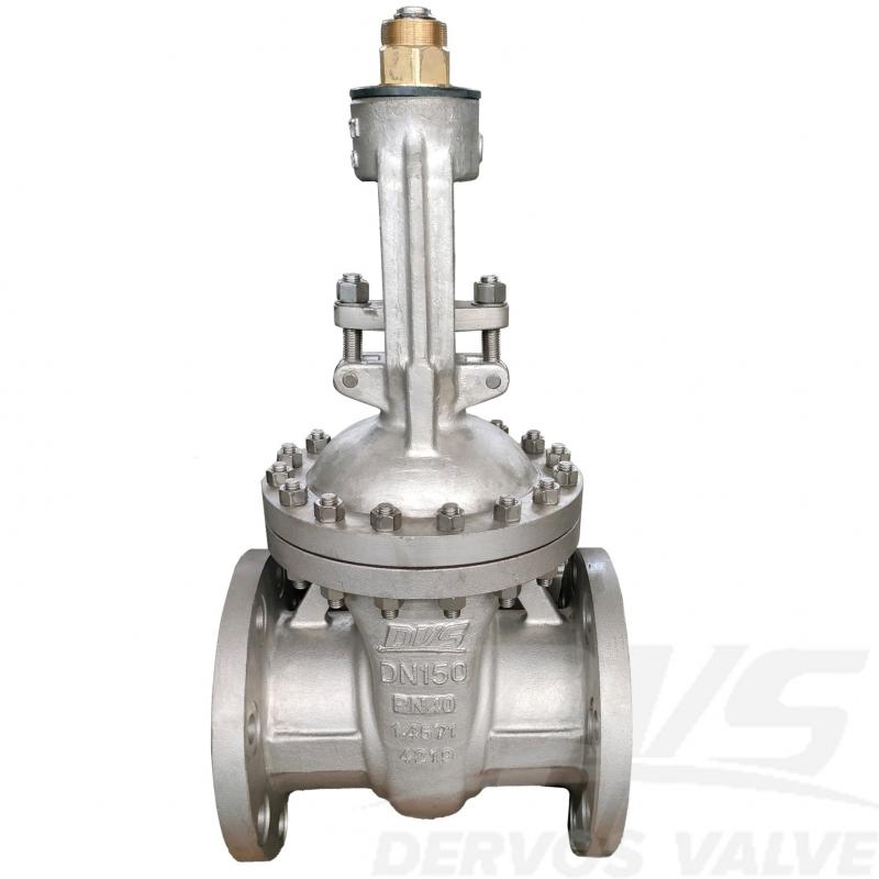
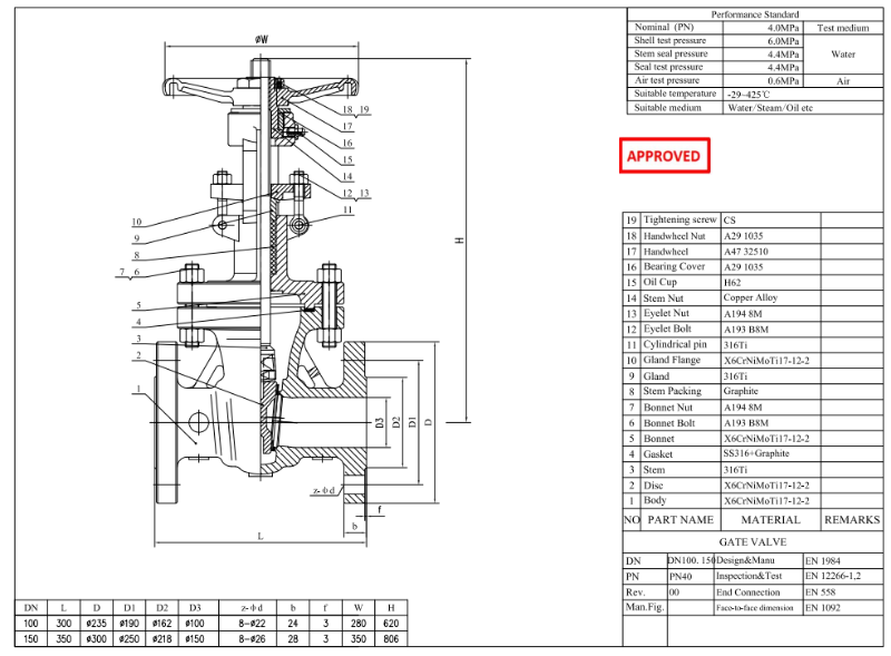
hand wheelDN150 PN40 Stainless Steel Gate Valve is made according to EN 1984 standard. The valve body is made of X6CrNiMoTi17-12-2. EN 1.4571 (AISI 316Ti) is widely used in medium- to high-temperature applications where resistance to intergranular corrosion and moderate chloride corrosion is required, especially in welded systems without post-weld heat treatment. Its connection mode is EN558. And it has Hand Wheel operation mode.
|
Type |
Stainless Steel Gate Valve |
|
Size |
DN150 |
|
Pressure |
PN40 |
|
Connection |
EN 558 |
|
Operation |
Hand Wheel |
|
Body Material |
X6CrNiMoTi17-12-2 |
|
Design Norm |
EN 1984 |
|
Face to Face dimension |
EN 1092 |
|
End connection |
EN 558 |
|
Test & Inspection Code |
EN 12266-1,2 |
|
Temperature |
-29 ~ 425°C |
|
Applicable Medium |
Water, Oil and Gas |
1.EN 1.4571 stainless steel construction provides strong resistance to pitting and stress corrosion in aggressive media.
2.DN150 PN40 configuration designed to EN 1984 standard ensures stable operation and tight isolation in medium-pressure pipelines.
If you are interested in our products and want to know more details,please leave a message here,we will reply you as soon as we can.
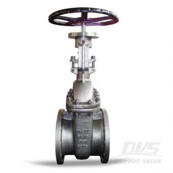
The stainless steel CF8M gate valve is designed with flange connection and handwheel operation per DIN 3352. The PN16 DN200 full port gate valve has OS&Y structure, resilient wedge and replaceable seat. Design Specifications Design and Manufacture: DIN 3352 End to End Dimension: DIN3202 Flange End: EN1092-1 Test & Inspection: EN12266-1/2 Design Feature -Full Bore Design -Superior flow rates & small friction loss -Low torque value for closing and opening the valve -Flexible wedge for better seating and ease of operation -Smooth finish and superior sealing for seat face -Every valve is manufactured with specific number on body for traceability Quick Detail Type Gate Valve Size DN 200 Pressure PN 16 Construction Bolted Bonnet, Rising Stem, Outside Screw and Yoke Connection Flange Connection Operation Handwheel Body Material Stainless Steel CF8M TrimMaterial Stainless Steel Temperature Range -268℃~+648℃ Medium Water, Oil and Gas Origin China Dervos Packaging Packaging is an important part we could never neglect. Dervos has a packaging process for each order to ensure a safe and clear delivery of the order.
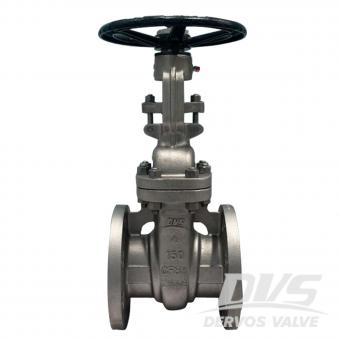
4" 150LB gate valve is made according to API 603 standard. The valve body is made of ASTM A351 CF8M+STL. It has the structural characteristics of bolt cover, elastic wedge and rising stem. Its test and inspection conform to API 598, and its operation mode is handwheel operation.
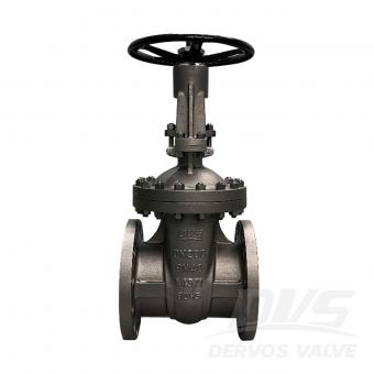
DN200 PN40 gate valve is made according to EN1984 standard. The valve body is made of 1.4571+STL. It has the structural characteristics of bolt cover, elastic gate, rising stem and bracket. Its connection mode is EN1092-1/B. And it has hand wheel operation mode.
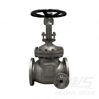
DN125 PN16 gate valve is made according to DIN 3352 standard. The valve body is made of 1.4408. It has the structural characteristics of bolt cover, rising stem, elastic wedge, with SS316 insulation jacket and structural length of 325mm. Its connection mode is RF EN1092-1 B1. And it has hand wheel operation mode.
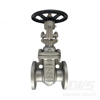
2" 150LB gate valve is made according to API 600 standard. The valve body is made of A351 CF3. It has the structural characteristics of bolt cover, rising stem bracket. Its connection mode is RF. And it has handwheel operation mode.
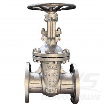
DN100 PN40 5A Duplex Stainless Steel Gate Valve is made according to EN 1984 standard. The valve body is made of ASTM A995 5A+STL. It has the structural characteristics of Full Bore, Bolted Bonnet, Rising Stem with Yoke, Flexible Wedge. Its connection mode is EN1092-1 B1. And it has hand wheel operation mode.
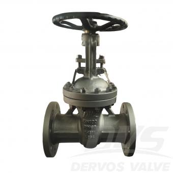
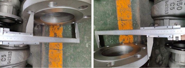
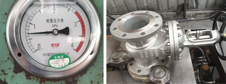
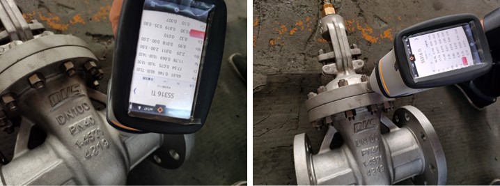
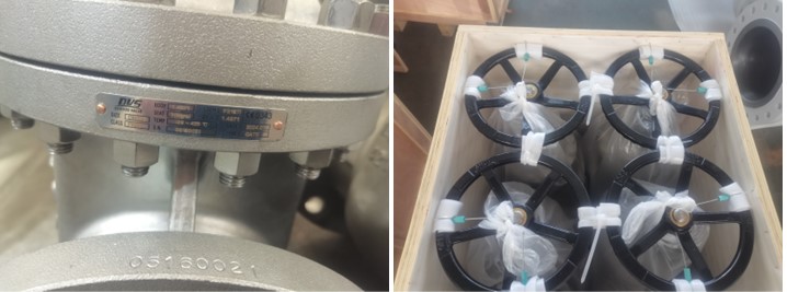
DN100 PN40 Stainless Steel Gate Valve is made according to EN 1984 standard. The valve body is made of X6CrNiMoTi17-12-2. EN 1.4571 (AISI 316Ti) is widely used in medium- to high-temperature applications where resistance to intergranular corrosion and moderate chloride corrosion is required, especially in welded systems without post-weld heat treatment. Its connection mode is EN558. And it has Hand Wheel operation mode. Product Parameters Type Stainless Steel Gate Valve Size DN100 Pressure PN40 Connection EN 558 Operation Hand Wheel Body Material X6CrNiMoTi17-12-2 Design Norm EN 1984 Face to Face dimension EN 1092 End connection EN 558 Test & Inspection Code EN 12266-1,2 Temperature -29 ~ 425°C Applicable Medium Water, Oil and Gas Features 1.Made from EN 1.4571 stainless steel, offering excellent corrosion resistance and high-temperature stability for PN40 pressure applications. 2.Gate valve design compliant with EN 1984 ensures reliable shutoff and long service life in industrial piping systems. Technical Drawing Dimension Checking Pressure Testing Spectrum Nameplate & Packing
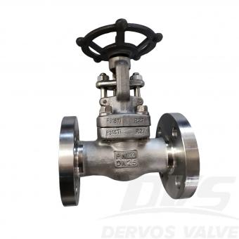
DN25 PN40 Flange Gate Valve is made according to API602 standard. The valve body is made of A182-F316Ti. Its connection mode is EN1092-1 B1. And it has Hand Wheel operation mode. Product Parameters Type Stainless Steel Gate Valve Size DN25 Pressure PN40 Connection EN1092-1 B1 Operation Hand Wheel Body Material A182-F316Ti Design Norm API 602 Flange dimension EN 1092 Material conform AISI/ASTM Test & Inspection Code EN 12266 Temperature -29 ~ 120°C Applicable Medium Water, Oil and Gas Features 1.F316Ti stainless steel body provides enhanced resistance to intergranular corrosion and elevated-temperature service. 2.DN25 PN40 gate valve designed to API 602 with EN1092-1 B1 flange ensures stable operation and tight isolation in process pipelines. Technical Drawing Dimension Checking Pressure Testing Spectrum Inspection Report
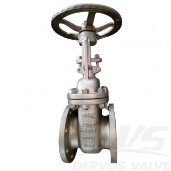
DN100 PN16 Stainless Steel Gate Valve is made according to DIN 3352 standard. The valve body is made of A351 CF8M+STL. It has the structural characteristics of Bolted Bonnet, Rising Stem, Flexible Wedge, Face-to-Face Dimensions per DIN 3202-F4. Its connection mode is RF. And it has handle operation mode. Product Parameters Type Stainless Steel Gate Valve Size DN100 Pressure PN16 Connection RF Operation Handle Body Material A351 CF8M+STL Design Norm DIN 3350 Face to Face DIN 3202-F4 Flange dimension EN 1092-1 Test & Inspection Code EN 12266 Temperature -29 ~ 425°C Applicable Medium Water, Oil and Gas Features 1.Rising stem Stainless Steel Gate Valve design ensures precise flow control and tight shut-off. 2.Rated PN16 with RF flange and DIN 3352 compliance, operated by handle for easy manual control. Technical Drawing Dimension Checking Pressure Testing Painting Nameplate & Packing Inspection Report
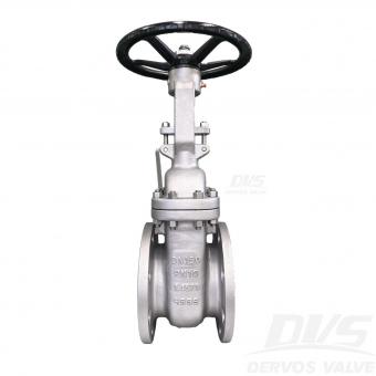
DN150 PN10 Stainless Steel Gate Valve is made according to EN 1984 standard. The valve body is made of 1.4571. It has the structural characteristics of Bolted bonnet, rising stem, flexible wedge. Its connection mode is EN 1092-1. And it has Handwheel operation mode. Product Parameters Type Stainless Steel Gate Valve Size DN150 Pressure PN10 Connection EN 1092-1 Operation Handwheel Body Material 1.4571+STL Design Norm EN 1984 Face to Face DIN 3202-F4 Flange dimension EN 1092-1 D Test & Inspection Code EN 12266 Temperature -46 ~ 200°C Applicable Medium Water, Oil and Steam Features 1. Stainless steel 1.4571 construction provides excellent corrosion resistance for demanding industrial applications. 2. Gate valve design complies with EN 1984 requirements for reliable isolation service. Dimension Checking Pressure Testing Nameplate & Packing
Copyright © 2015-2026 DERVOS VALVE CO.,LTD.All Rights Reserved Blog / Sitemap / XML / Privacy Policy