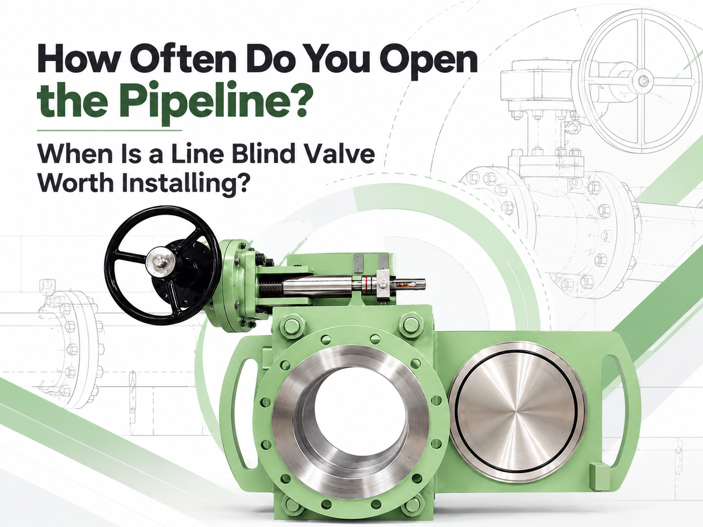
A line blind valve is worth evaluating when a pipeline is blinded several times a year, or when one conventional changeover causes hours of shutdown, lifting work or significant exposure to hazardous residue. No universal cycle count guarantees payback. A large critical line operated twice a year may justify the investment, while a small accessible line operated monthly may not. The decision should be based on the cost and risk of each complete isolation event, not frequency alone. There Is No Standard “Two Operations per Year” Rule Some suppliers use one or two annual changeovers as a screening threshold. That can start a discussion, but it is not an engineering rule. Frequency has very different consequences on a DN50 utility line and a DN600 process-gas main. For a preliminary review, the following bands are useful but not mandatory: Blinding frequency Initial interpretation Once per major turnaround or less A removable blind or spectacle blind is often more economical. One to three times per year Compare labor, lifting, outage duration and medium risk carefully. Quarterly to monthly A quick-action line blind is normally a strong candidate. Weekly or more often Purpose-built or automated isolation deserves detailed review; also confirm that a line blind is suitable for the required cycle duty. A low operating frequency can still support installation when every event requires scaffolding, a crane, several pipefitters or a long production interruption. Conversely, frequent operation does not justify a line blind if the process cannot accommodate its pressure, temperature, materials or maintenance needs. Count the Complete Changeover Traditional blinding is more than moving a plate. After the line is made safe, workers loosen bolting, spread the flange joint, handle the blind or spacer, replace gaskets, restore alignment, tighten the joint and complete leak checks. Large sizes add rigging and access equipment. A quick-action line blind keeps the spectacle or sliding plate supported inside the installed assembly. Manufacturer literature commonly reports one-person changeover in minutes rather than the man-hours needed for conventional flange work. Those figures are useful for screening, but the project calculation should use the plant’s own procedures and recorded shutdown times. Use a simple comparison: Annual avoided cost = operations per year x cost avoided per operation Avoided cost may include pipefitter hours, rigging, scaffolding, gaskets and bolting, leak testing and the production value of saved time. Keep categories separate to avoid double counting. Compare the annual saving with the line blind’s additional installed price and maintenance cost. Risk Can Matter More Than Simple Payback Repeated flange separation creates opportunities for residual-medium exposure, damaged flange faces, poor alignment and inconsistent bolt load...
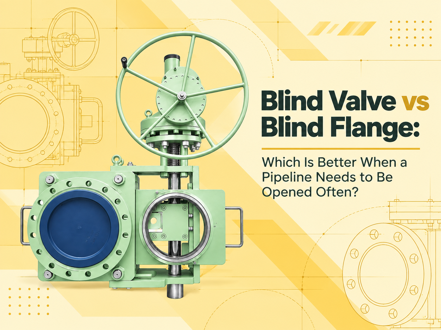
When a pipeline must be opened and positively isolated often, a line blind valve is usually the better choice. It keeps the blind mechanism permanently installed and lets operators change between open and blocked positions without repeatedly removing a bolted end closure. A blind flange costs less and has fewer moving parts, but it is better suited to closing a pipe end that will remain closed for long periods. This answer assumes that “blind flange” means a solid flange bolted to the end of a pipe or nozzle. A spectacle blind or a removable spade installed between two flanges is a different device, although it creates a similar solid-metal isolation barrier. Frequent Opening Changes the Cost Calculation The purchase price favors the blind flange. Its construction is simple, and maintenance is largely limited to checking the flange face, gasket, studs and nuts. If the closure will be disturbed only during an occasional turnaround, that simplicity is difficult to beat. Repeated opening changes the picture. Removing a blind flange requires the line to be shut down, depressurized, drained or purged, and verified safe. The bolts must then be loosened, the flange supported and the sealing faces separated. Larger flanges may require lifting equipment. Reassembly introduces a new gasket, controlled bolt tightening and a leak test. None of these steps is unusual, but repeating them turns a low-cost component into a labor-intensive operating method. A line blind valve also requires the line to be isolated and depressurized before changing position unless its approved design and operating procedure explicitly state otherwise. Its advantage is mechanical handling: the plate, spacer or sliding element remains captured in the body, and the mechanism separates, moves and reclamps the sealing faces. Manual gearing may suit moderate operating forces; electric, pneumatic or hydraulic actuation may be justified for large sizes or remote operation. The Blind Valve Reduces Handling but Adds Equipment to Maintain For frequent switching, a blind valve can shorten the task and reduce repeated handling of heavy plates, bolts and gaskets. Its open or closed position is normally visible from the external plate or position indication, which helps field verification. It also avoids repeatedly forcing connected piping apart to insert or remove a blind. Those benefits come with additional maintenance. Guides, screws, gearboxes, hydraulic components, seals and interlocks must remain functional. Product deposits or corrosion can obstruct plate travel, while damaged sealing surfaces can prevent reliable reclamping. The installation therefore needs drainage, cleaning access and enough surrounding clearance to complete the full movement and service the mechanism. A blind flange has no operating mechanism to seize. However, frequent removal can damage flange faces, stretch or corrode bolting, disturb pipe al...

Yes, a line blind valve can usually be added to an existing pipeline, but the job is rarely as simple as cutting out a short section and inserting the valve. The valve must fit the existing flanges and pressure class, but that is only the first check. It also needs room to release the sealing mechanism, move the blind plate, reclamp, and remain accessible for future operation. The modified pipework must then be supported, inspected and tested before it returns to service. A valve that fits between the pipe ends but cannot complete its operating stroke is not a workable retrofit. Start With the Full Operating Envelope Face-to-face length tells you how much pipe must be removed. It does not tell you how much space the valve needs once it starts moving. A swing-type line blind needs a clear arc for the spectacle plate. That space may extend well beyond the valve body. Nearby pipework, cable trays, handrails, platforms, insulation and structural steel can all block the movement. A sliding design needs enough space for the plate to travel sideways or vertically. The drive mechanism, gearbox, hydraulic cylinder or actuator adds another clearance requirement. Check the manufacturer’s general arrangement drawing for: ● Face-to-face length ● Maximum body width and height ● Full plate travel or swing radius ● Handwheel, gearbox or actuator clearance ● Space needed to remove seals and internal parts ● Lifting points and rigging access ● Safe standing position for the operator Do not measure only from the valve centerline. A gear operator may clear the adjacent pipe while the blind plate still strikes it halfway through the stroke. Orientation matters too. On vertical piping, some designs require a specific mechanism position so gravity cannot pull an unclamped component out of place. Manufacturer instructions for one cam-operated design, for example, call for the cam mechanism to be installed below the spectacle plate on a vertical line. Check the Existing Pipeline Before Choosing the Valve Old drawings are useful, but the final fit should be based on field measurements. Existing pipelines may have been repaired, rerouted or pulled out of alignment since the original drawings were issued. Record the actual: ● Pipe outside diameter and schedule ● Flange standard, size, class and facing ● Distance between flange faces or proposed cut points ● Pipe centerline and flange orientation ● Available movement in the existing line ● Insulation and heat-tracing thickness ● Nearby supports, guides and expansion joints ● Operating and design pressure and temperature ● Medium, corrosion allowance and material specification Flanges that appear similar may use different drilling, facing or dimensions. Confirm the complete flange designation rather than relying on nominal size and pressure class alone. The selected gasket must also suit the flange facing, medium, temperature and surface finish. Installing a new valve betw...
Payment:
30% when order confirmed, 70% before shipmentProduct Origin:
chinaColor:
CustomizationShipping Port:
Shanghai, ChinaLead Time:
30~60 days Ex Works after order confirmationMaterial:
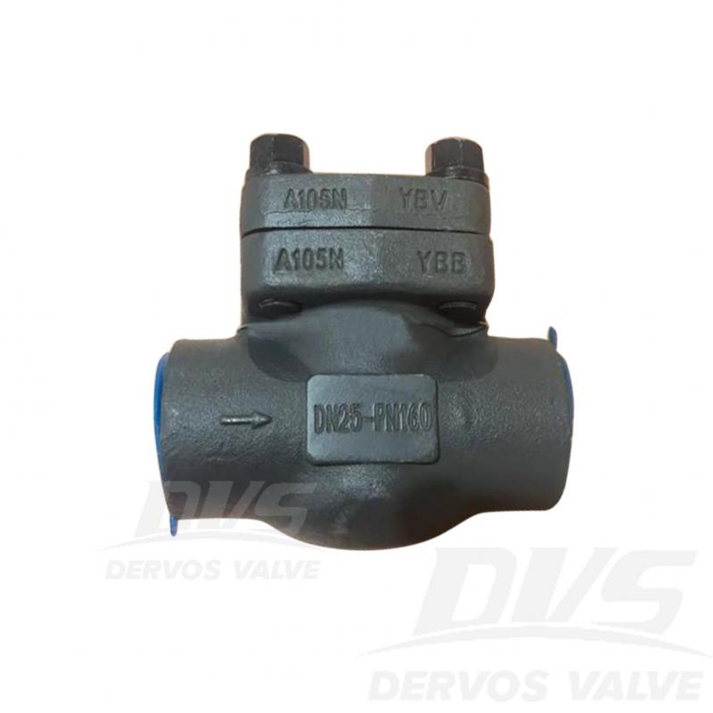
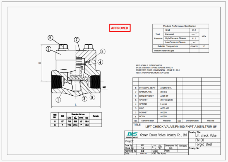
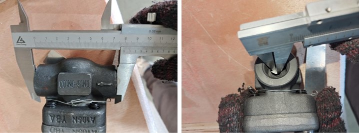
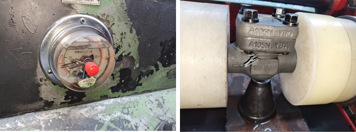
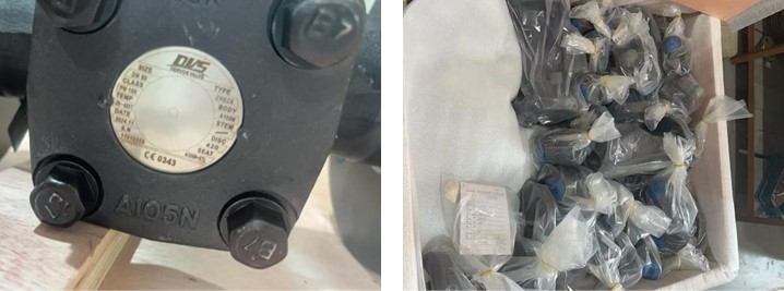
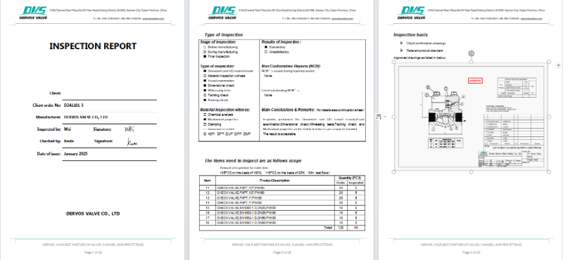
A105NDN25 PN160 Lift Check Valve is made according to ASME B16.34 standard. The valve body is made of A105N. It has the structural characteristics of Lift-type, spring-loaded and structural length of 230mm. Its connection mode is EN1092-1 D.
|
Type |
Lift Check Valve |
|
Size |
DN25 |
|
Pressure |
PN160 |
|
Connection |
EN1092-1 D |
|
Body Material |
A105N |
|
Design Norm |
API60 |
|
Test & Inspection Code |
EN12266 |
|
Temperature |
-29 ~ 425°C |
|
Applicable Medium |
Water, Oil and Gas |
1.The lift-type disc provides reliable non-return performance and helps prevent reverse flow.
2.The A105N forged steel body ensures high strength and durability for PN160 high-pressure service.
If you are interested in our products and want to know more details,please leave a message here,we will reply you as soon as we can.
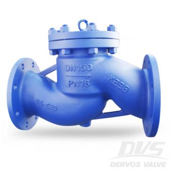
The cast steel lift non return check valve is designed with piston type disc, bolted bonnet, and PN16 RF flange. The spring loaded check valve conforms to DIN 3356. Quick Detail Type Check Valve ( Non-return Valve) Nominal Diameter DN 150 NominalPressure PN 16 Construction Lift Type / Piston Type, Bolted Bonnet Connection Flanged Connection Design & Manufacture DIN 3356 End to End EN 558 Connection EN 1092 Test & Inspection EN 12266 Body Material Carbon Steel GS C25 Media W.O.G. Product Range Body material: CS, SS, Alloy Steel, CI, Bronze, Brass Size Range: 2”~12” (DN50~DN300) End Type: Butt Weld, Socket Weld, Flanged, Screwed Pressure Range: 150lbs~2500lbs (PN16~PN420) Temperature Range: -46℃~ +425℃ Related Knowledge What is a piston check valve? Usually, we have swing type check valve and lift type check valve. A piston check valve and ball check valve both belong to lift type check valve. In a lot of cases, a piston check valve use spring to retain the disc in closed position. The structure of a piston check valve is very similar to the globe valve just without manual operation. Due to its piston type disc and superior leak tight characteristic, the piston check valves are suitable for small size and high pressure conditions.
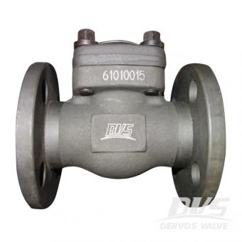
The forged steel lift check valve is designed with class 150 pressure and 1 inch nominal size according to standard API 602. We also call it as piston check valve. Quick Detail Type Check Valve Size 1'' DesignPressure 150LB Construction Lift Type, Piston Type Connection RF Flange Design & Manufacture API 602 End to End ASME B16.10 Connection ASME B16.5 Pressure & Temp ASME B16.34 Test & Inspection API 598 Body Material ASTM A105N Trim Material Trim 5 Temp Range -29℃~+425℃ Media W.O.G. Dimension Checking Pressure Tesing Packing
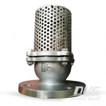
The 2 inch 150LB foot valve is made of stainless steel.
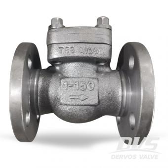
Due to its simple flow efficient and virtually maintenance-free design, thestainless steel ball checkvalve is commonly specified and used in submersible waste water lift stations.
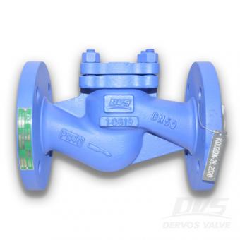
This spring loaded check valve, made according to DIN3840, requires no gravity or backflow pressure to work or actuate.It’s body material 1.0619 enable the valve to work under great heat and It’s spring can accommodate a wide range of temperature, too.
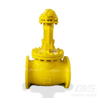
Chinese Valve manufacturer Dervos supplies Check Valve that featured with through conduit, plug type disc and replaceable seat. Expect these 14 inch 150LB check valve, other types valves of different materials, sizes are also available.
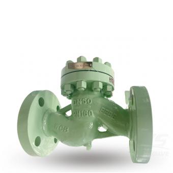
The DN50 PN160 spring loaded lift check valve, made of Cast Steel, is powered by flow and differential pressure with assistance from spring pressure. And it requests no human intervention is required to function, easy to use.
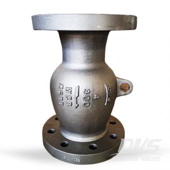
The stainless steel non return valve features in non slam type disc, INCONEL X750 spring, WCB valve body. This valve owns an excellent dynamic performance and minimizes vibrations and noise.
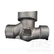
1" 2500LB check valve is made according to ASME B16.34 standard. The valve body is made of F316L. It has the structural characteristics of lifting type, pressure self-sealing, conventional diameter. Its connection mode is FNPT.
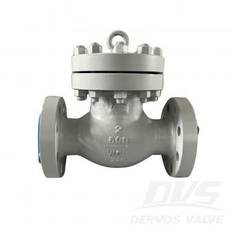
2" 600LB check valve is made according to BS1868 standard. The valve body is made of A216 WCB. It has the structural characteristics of lifting type, bolt cover and body valve seat. Its connection mode is RF.
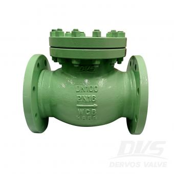
DN100 PN16 check valve is made according to EN12516-1 standard. The valve body is made of ASTM A216 WCB+STL. It has the structural characteristics of lifting type with spring. Its connection mode is EN1092-1 B.
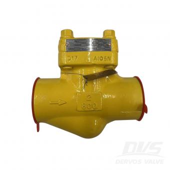
2" 800LB lift check valve is made according to API 602 standard. The valve body is made of ASTM A105N+STL. It has the structural characteristics of lift type. Its connection mode is SW.
Copyright © 2015-2026 DERVOS VALVE CO.,LTD.All Rights Reserved Blog / Sitemap / XML / Privacy Policy