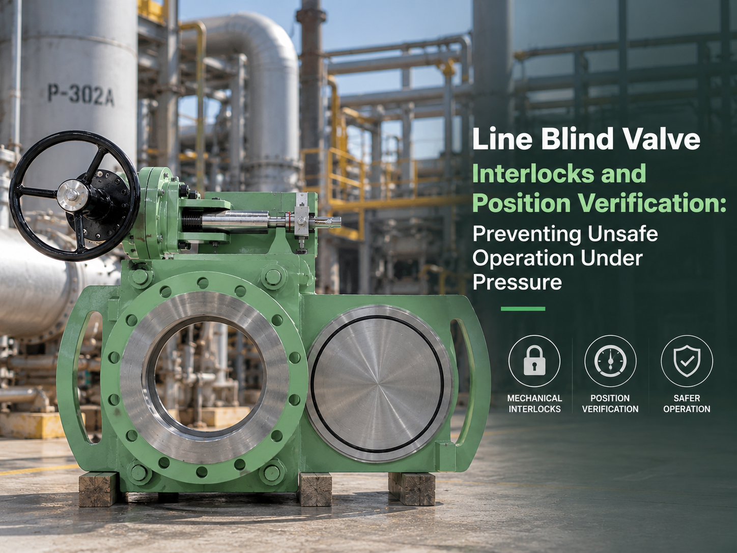
A line blind valve creates positive isolation only after the solid plate is correctly positioned, fully restrained and capable of withstanding the process pressure. The dangerous part is the transition between the open and blinded states: many designs temporarily release the clamping force or expose part of the line while the plate moves. An interlock must therefore control an isolation sequence, not merely prevent the actuator from starting. A “closed” lamp, a limit-switch signal or a zero-pressure indication is useful evidence, but none of them independently proves that the line is safe to open. Why Operating Sequence Matters More Than Actuator Type Whether the line blind is manual, electric or hydraulic, it should not move until the process has been isolated, depressurized and drained. A powered actuator makes remote operation possible, but it also allows an incorrect command to be executed rapidly and from a location where the operator cannot see a release. A robust sequence normally requires: 1. Upstream and downstream block valves are closed and locked or otherwise secured. 2. The trapped section is vented or drained to a suitable disposal system. 3. Pressure has fallen below the project-defined permissive value. 4. A field operator or independent authorization confirms that the isolation arrangement is correct. 5. The line blind clamping mechanism is released. 6. The plate moves completely into the open or blind position. 7. The mechanism reclamps and mechanically secures the plate. 8. Final position and clamping status are recorded before process conditions are restored. This sequence matters because closing the adjacent valves does not remove trapped pressure. A blocked drain, leaking upstream valve, vaporizing liquid or thermal expansion can repressurize the cavity after an initial pressure reading. AIG therefore recommends upstream isolation, bleed and pressure indication for line blind installations, with double block and bleed considered where a large hazardous inventory could be released. It also identifies pressure-sensing interlocks, controlled keys and secondary isolation verification as possible protection layers. What Position Feedback Actually Proves Position verification should answer three separate questions: · Is the solid or open plate in the intended location? · Is the plate fully clamped and mechanically retained? · Is the surrounding process condition safe for movement? These are different states and should not be represented by one shared switch. A limit switch normally confirms that the component driving the switch has reached a calibrated endpoint. It does not automatically prove that the blind plate followed the drive mechanism, that the plate is centred between the seats, or that the clamping load is adequate. A loose cam, bent bracket, damaged linkage or incorrectly adjusted switch can produce...
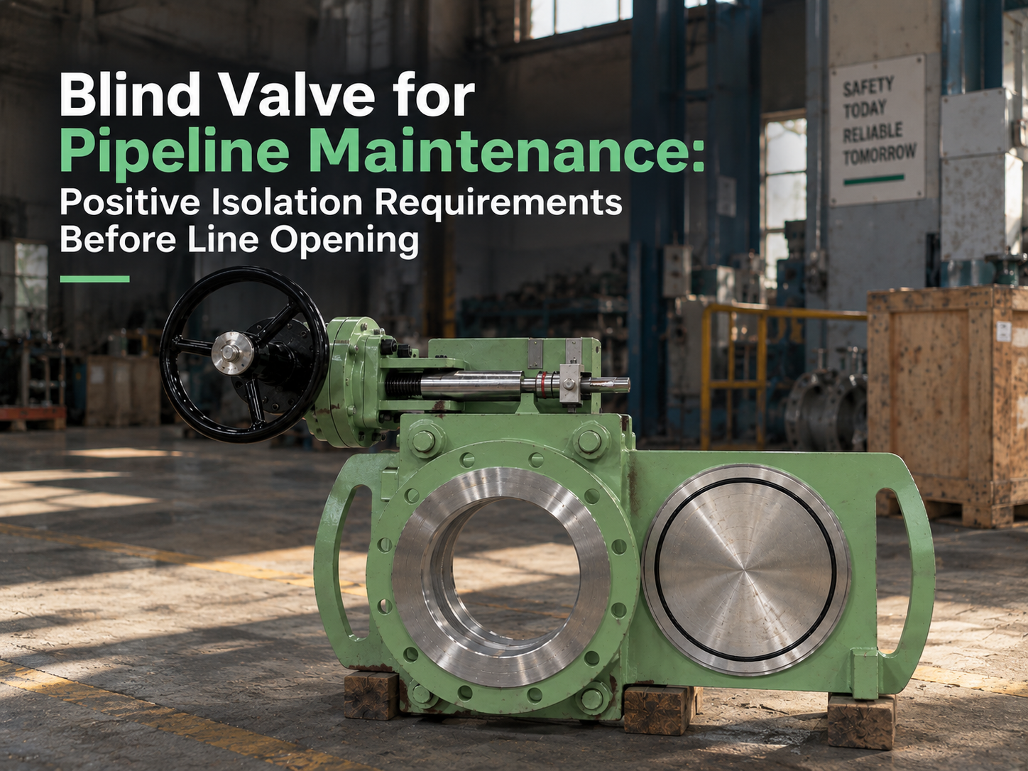
Before a pipeline is opened, a blind valve should be treated as one part of an isolation system, not as a permit by itself. Its value is that it can place a visible physical barrier in the line, but that barrier only becomes meaningful when the site has also isolated, depressurized, drained, vented, locked, tagged, tested, and verified the correct section of piping. Line opening is the moment when weak isolation becomes real. A closed valve may pass. A bleed point may be plugged. A drawing may be outdated. Liquid may remain trapped in a low point. Gas may migrate from an unexpected connection. This is why positive isolation for pipeline maintenance has to be judged as a chain of proof, not a single valve feature. The Isolation Boundary Must Be Proven on the Drawing and in the Field The first requirement is knowing exactly what is being isolated. Maintenance teams usually start from the P&ID or isolation plan, but the field verification is just as important. Tie-ins, bypasses, drains, vents, sample points, small-bore branches, equalizing lines, instrument connections, and thermal relief paths can all create energy routes around the expected isolation point. A blind valve installed in the correct location can give strong physical isolation. Installed on the wrong side of a branch connection, it may protect the main line while leaving the work face exposed to pressure or hazardous material from a side path. That is not a valve failure; it is an isolation boundary failure. Before line opening, the isolation plan should identify the upstream and downstream sources, the section to be opened, all possible re-pressurization routes, and the exact valve position required. The field check should confirm tag numbers, flow direction, blind position, locking status, and whether the valve can be seen and reached safely. Positive Isolation Is More Than Seat Leakage A blind valve differs from a normal shutoff valve because it uses a solid blind plate, spectacle plate, or sliding/swinging blind mechanism to block the bore. This reduces reliance on seat tightness alone. For maintenance work involving flange breaking, equipment opening, hot work, confined-space entry, or hazardous media, that physical barrier can be more defensible than a closed gate, globe, or ball valve. Still, the phrase “positive isolation” should not be used loosely. The blind must be in the correct position, fully seated, mechanically restrained, locked or tagged according to the site procedure, and confirmed by position indication that maintenance personnel can understand. If the mechanism is stiff, partly engaged, poorly marked, or difficult to verify from the work area, the valve’s theoretical advantage becomes weaker. The seal arrangement also matters. Some line blind valves rely on resilient seals, graphite seals, metal seating surfaces, or combined sealing designs depending on temperature, pressure, and ...
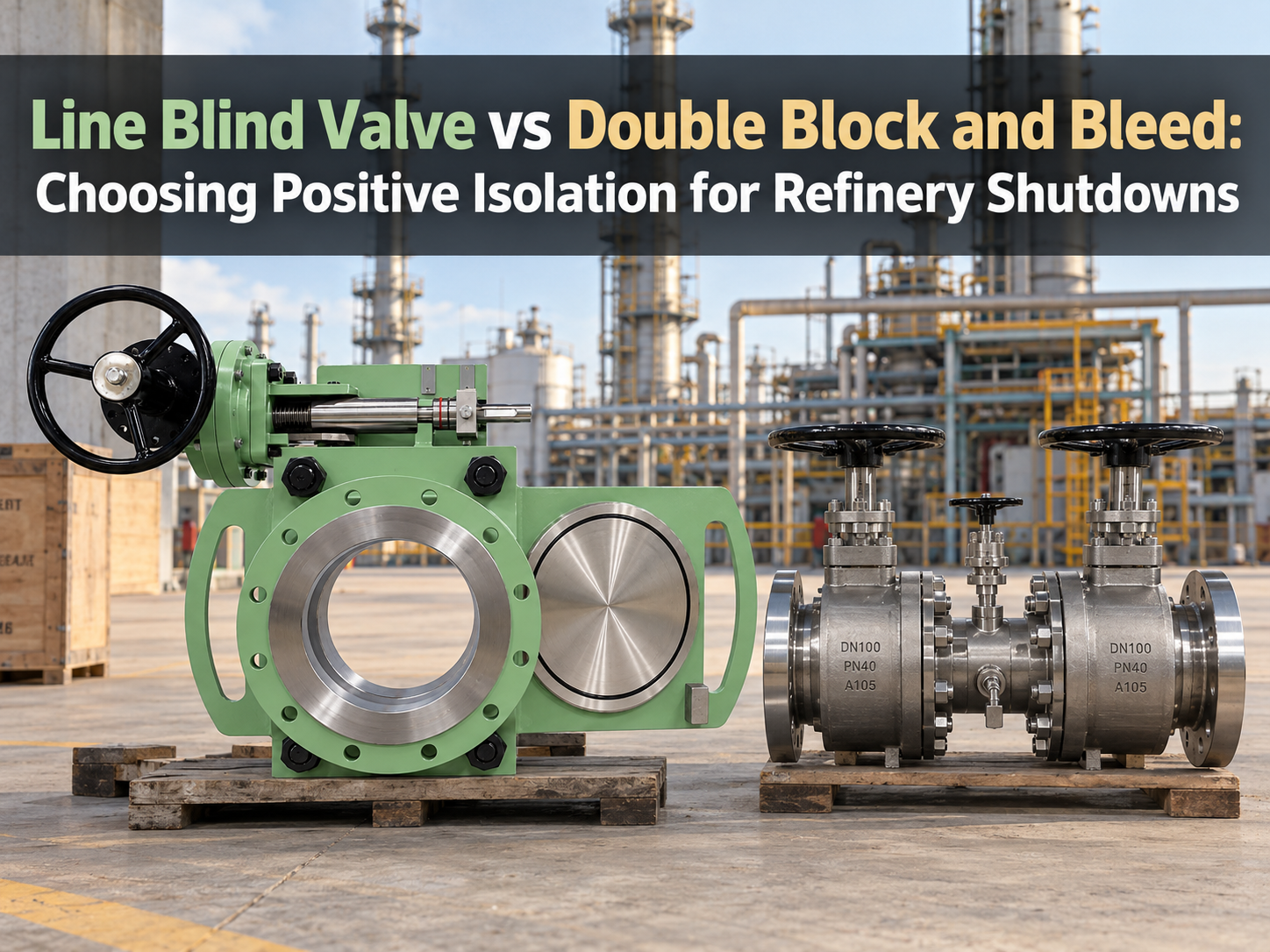
In refinery shutdowns, the choice between a line blind valve and double block and bleed is not a contest between one safe method and one unsafe method. Both can be valid isolation methods, but they control risk in different ways. A line blind valve creates isolation by moving a solid blind plate into the pipeline bore. The isolation is visible and mechanical. A double block and bleed arrangement isolates by closing two barriers and opening a bleed or vent between them, so trapped pressure or leakage can be released or monitored. The engineering question is not only “which one seals better?” It is “what work will happen after isolation, and how much reliance can the site accept on valve seats, bleed monitoring, and procedure control?” Shutdown Work Changes the Isolation Standard Routine instrument work, sampling maintenance, or short inspection tasks may justify a different isolation method from hot work, vessel entry, flange breaking, or long-duration turnaround maintenance. In a refinery, the same hydrocarbon line may be low-risk in one task and high-risk in another because the exposure changes. A DBB arrangement is useful when the work needs fast, verifiable valve isolation without moving a blind plate into the bore. The bleed point gives operators a way to confirm whether pressure is trapped between the isolation points or whether one of the seats may be passing. For many operating teams, that makes DBB practical for frequent or temporary isolation where breaking containment would add more work and more exposure. A line blind valve becomes stronger when the job needs visible physical separation from a live or potentially live system. If the isolated equipment will be opened, entered, welded, cleaned, or left out of service during a shutdown window, a solid blind plate reduces dependence on seat tightness. The valve still needs proper operation, locking, marking, and testing, but the core barrier is no longer only a seating surface. Where DBB Earns Its Place DBB is attractive because it can reduce downtime. A compact DBB valve or a two-valve DBB arrangement can isolate, bleed, and verify without removing a spool or installing a separate blind flange. For refinery units with many small-bore connections, drains, vents, sampling points, or instrument take-offs, that speed matters. The risk with DBB is that its safety case still depends on seat integrity, correct bleed routing, pressure monitoring, and disciplined lockout practice. If the bleed is not routed to a safe location, it may create a release hazard. If operators close two valves but do not prove the bleed, the system may only look isolated. If the valves have seat damage from coke, catalyst fines, thermal cycling, corrosion, or debris, the bleed point may reveal leakage rather than eliminate it. This is why DBB should be described clearly in the shutdown plan. Does the project mean two separate inline isolation valves with a drain...
Payment:
30% T/T When Order, 70% T/T Before ShipmentProduct Origin:
ChinaColor:
CustomizationShipping Port:
Shanghai ChinaLead Time:
30~55 days Ex Works After Order ConfirmationMaterial:
Stainless SteelMethod of Operation:
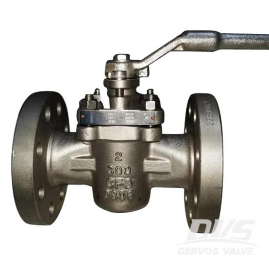
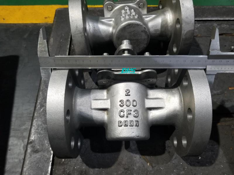
LeverThe PTFE sleeved plug valve is made of CF3 body and plug as per API 6D. The valve owns the feature of reduced port and good sealing performance. We call this type of valve as non lubricated plug valve or self lubricated plug valve.
Quick Detail
|
Type |
Plug Valve |
|
Size |
2'' |
|
DesignPressure |
300LB |
|
Construction |
Sleeved Type, Non Lubricated Type, Soft Seat |
|
ConnectionType |
Flange |
|
Operation |
Lever Operation |
|
Design Code |
API 599, API 6D |
|
Face to Face |
ASME B16.10 |
|
End Connection |
ASME B16.5 |
|
Pressure & Temp |
ASME B16.34 |
|
Test & Inspection |
API 598 |
|
Body Material |
CF3 |
|
Temperature Range |
-29℃~+120℃ |
|
Application |
Water, Oil, Gas |
Dimension Checking
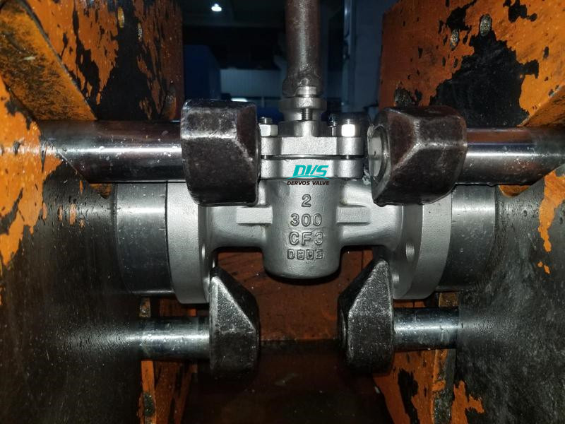
Hydrostatic Testing
If you are interested in our products and want to know more details,please leave a message here,we will reply you as soon as we can.
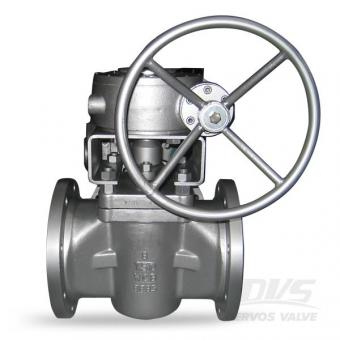
The 6 inch sleeved plug valve features in non lubricated design and soft seat. The full port plug valve is made of carbon steel body and PTFE seat as per API 6D, with Class 150 flange connection. Quick Detail Type Plug Valve Size 6'' Design Pressure 150LB Construction Self-Lubricated Type, Sleeved Type, Soft Seat Connection Type RF Flange Operation Gearbox Operation Design Code API 599 Face to Face ASME B16.10 End Connection ASME B16.5 Pressure & Temp ASME B16.34 Test & Inspection API 598 Body Material A216 WCB Temperature Range -29℃~+425℃ Application Water, Oil, Gas Material & Dimension No Part Name Carbon steel to ASTM Stainless steel to ASTM WCB LCB CF8 CF8M CF3 CF3M 1 Body A216 WCB A350 LCB A351 CF8 A351 CF8M A351 CF3 A351 CF3M 2 Bonnet A216 WCB A350 LCB A351 CF8 A351 CF8M A351 CF3 A351 CF3M 3 Plug A105 A182 F304 A351 CF8 A351 CF8M A351 CF3 A351 CF3M 4 Stem A182 F6 A182 F6 A182 F304 A182 F316 A182 F304L A182 F316L 5 Seat Ring PTFE 6 Gasket PTFE or Stainless Steel and Graphite 7 Stem Seat PTFE PTFE PTFE PTFE PTFE PTFE 8 Small spring 17-17PH 9 Small ball A182 F304 or A182 F316 10 Gland A182 F6 A182 F6 A182 F304 A182 F316 A182 F304L A182 F316L 11 Gland Flange A216 WCB A350 LCB A351 CF8 A351 CF8M A351 CF3 A351 CF3M 12 Stem packing PTFE or Graphite 13 Bonnet bolt A193 B7 or A320 L7 or A320 B8 or A193 B8M 14 Bonnet nut A194 2H or A194 4 or A194 8 Class 150 DN mm 15 20 25 40 50 65 80 100 150 200 250 300 NPS in 1/2 3/4 1 1 1/2 2 2 1/2 3 4 6 8 10 12 L(RF) mm 108 117 127 165 178 191 203 229 394 457 533 610 in 4.25 4.6 5 6.5 7 7.5 8 9 15.5 18 21 24 L1(BW) mm 140 152 165 190 216 241 283 305 457 521 559 635 in 5.5 6 6.5 7.48 8.5 9.5 11.13 12 18 20.5 22 25 L2(RTJ) mm 119 129.7 139.7 178 191 203 216 241 406 470 546 622 in 4.69 5.11 5.5 6.9 7.5 8 8.5 905 16 18.5 21.5 24.5 H mm 59 63 75 92 153 165 195 213 272 342 495 580 in 2.3 2.5 2.95 3.74 6.02 6.5 7.68 8.39 10.7 13.5 19.5 22.85 D(W) mm 130 130 160 230 400 400 600 850 1100 1500 350* 350* in 5.1 5.1 6.3 9 15.74 15.74 23.62 33.46 43.3 59 13.8 13.8 Weight (Kg) RF 2.3 3 4.5 7 15 20 25 40 97 160 240 390 BW 2.0 2.5 3.8 5.8 12 17 21 36 92.8 154 227 365
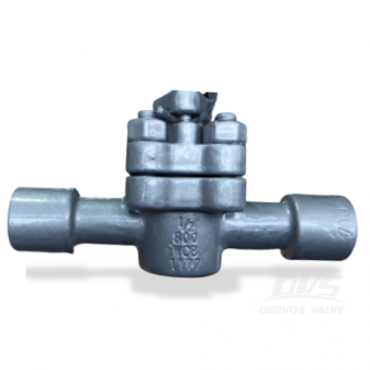
This 1/2 Inch plug valve is made of A216 WCB, according to API598.With little required maintenance and trouble-free operation, a high integrity bubble-tight seal is provided both in-line and to atmosphere.
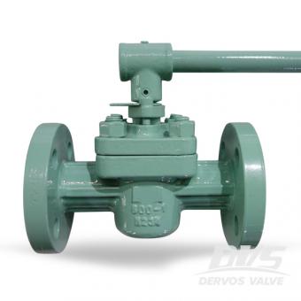
The 1 inch sleeved type plug valve is made of A216 WCB as per API 599. Thanks to its PTFE seat, the valve has excellent sealing and anti-corrosion performance. The valve is capable in working condition lower than 180 degree.
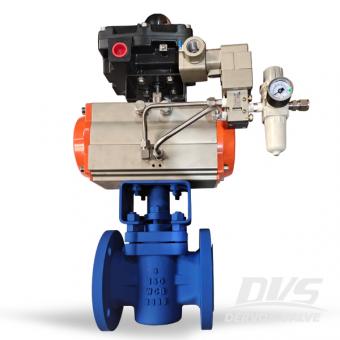
Non-Lubricated, Sleeved Plug Valves incorporate state-of-the-artPPL seat design. With little required maintenance and trouble-free operation, the 3 inch 150 LB valve will ensure a high integrity bubble-tight seal.
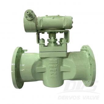
DN250 PN25 plug valve is made according to API599 standard. The valve body is made of A216 WCB. It has the structural characteristics of soft sealing plug valve. Its connection mode is RF. And it has turbine operation mode.
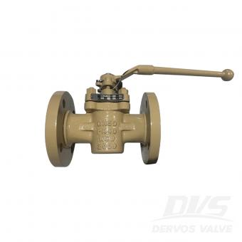
DN50 PN40 plug valve is made according to API 599 standard. The valve body is made of A216 WCB. It has the structural characteristics of ferrule type, reduced diameter. Its connection mode is RF. And it has lever operation mode.
Copyright © 2015-2026 DERVOS VALVE CO.,LTD.All Rights Reserved Blog / Sitemap / XML / Privacy Policy