What is a Wafer Ball Valve?
Jul 11, 2024
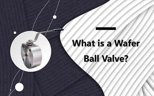
The wafer ball valve is a common industrial valve, widely used in various piping systems due to its unique structural design and superior performance. Definition A wafer ball valve is a valve that controls fluid flow by rotating the valve core. Its body is designed in a wafer style, meaning the valve is clamped between two pipeline segments with bolts, eliminating the need for additional space required by traditional flange connections. Wafer ball valves are typically used for applications involving shutoff, distribution, and changing the flow direction. Structural characteristics 1. Compact Design: The wafer ball valve features a wafer-style design, making its structure compact and requiring minimal installation space, ideal for pipeline systems with limited space. 2. Lightweight: Due to the elimination of flanges and bolt connections, the wafer ball valve is relatively lightweight, helping to reduce the load on the pipeline system. 3. Easy Installation and Maintenance: The installation and removal of wafer ball valves are very convenient; simply sandwich the valve between the pipelines and secure it with bolts. This design greatly simplifies the installation and maintenance process of the valve. 4. Good Sealing Performance: Wafer ball valves typically use soft or hard sealing structures, ensuring excellent sealing performance and effectively preventing fluid leakage. Working principle The working principle of the wafer ball valve is relatively simple, primarily involving the rotation of the valve core (ball) to control fluid flow. The specific process is as follows: 1. Opening the valve: When the handle or actuator is rotated, the valve core (ball) rotates 90 degrees, aligning the valve passage with the pipeline passage, allowing fluid to pass through freely. 2. Closing the valve: By rotating the handle or actuator in the opposite direction, the valve core (ball) rotates another 90 degrees, making the valve passage perpendicular to the pipeline passage, blocking the fluid flow and achieving the shut-off function. Advantage 1. Space-saving: The compact design of wafer ball valves takes up less space, making them particularly suitable for installations with limited space. 2. Lightweight: Compared to traditional flanged ball valves, wafer ball valves are lighter, making them easier to transport and install. 3. Easy installation: The installation process of wafer ball valves is simple and quick. They only need to be clamped between the pipes and fixed with bolts, eliminating the cumbersome steps of flange connections. 4. Excellent sealing performance: Wafer ball valves use high-quality sealing materials, providing superior sealing performance suitable for applications requiring high sealing standards. 5. Versatile applications: Wafer ball valves are suitable for various industrial piping systems, such as water treatment, chemical, oil and gas, pharmaceutical, and food industries. Application 1. Water treatment systems: Used to control water flow an...
View More