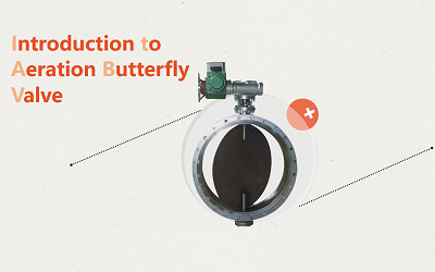
English

English

Get a Quote
Industry Knowledge
  • How to Install the Valve Gasket?
    How to Install the Valve Gasket? Jun 07, 2023
    Sealing gasket is a commonly used sealing spare part for machinery, equipment, etc. It is a material that plays a sealing role. Correct installation can ensure sealing performance and smooth operation of the equipment, otherwise it will damage the sealing gasket. Next, let's take a specific look at what to do. The correct installation of gaskets should be carried out when the flange connection structure or threaded connection structure, sealing surface, and gasket have been inspected without any doubt, and other valve components are intact and undamaged. 1. Before installing the gasket, apply a layer of graphite powder or lubricant mixed with engine oil (or water) to the sealing surface, gasket, thread, and rotating parts of the bolt and nut. The gasket and graphite should be kept clean. 2. The gasket should be installed on the sealing surface in a moderate and correct manner, without deviation, and should not extend into the valve chamber or rest on the shoulder. 3. Only one gasket is allowed to be installed, and it is not allowed to install two or more gaskets between the sealing surfaces to eliminate insufficient clearance between the two sealing surfaces. 4. The sealing of elliptical gaskets should ensure that the inner and outer rings of the gasket come into contact, and the two ends of the gasket should not come into contact with the bottom of the groove. 5. The installation of the O-ring should not only meet the design requirements for the ring and groove, but also have an appropriate amount of compression. On the premise of ensuring sealing, the smaller the compression deformation rate, the better, which can extend the service life of the O-ring. 6. Before installing the gasket, the valve should be in the open position to avoid affecting installation and damaging the valve components. When covering, it should be aligned with the position and should not be pushed or pulled into contact with the gasket to avoid displacement and scratches on the gasket. 7. The installation of gaskets for bolted or threaded connections should ensure that the gaskets are in a horizontal position (threaded gaskets with wrench positions should not be used with pipe wrenches). 8. Before tightening the gasket, it is necessary to have a clear understanding of the pressure, temperature, properties of the medium, and material characteristics of the gasket to determine the pre tightening force. The preload should be minimized as much as possible without leakage during pressure testing. 9. After tightening the gasket, it is necessary to ensure that there is a pre tightening gap between the connecting parts in case of gasket leakage. 10. When working at high temperatures, bolts will experience high-temperature creep, stress relaxation, and increased deformation, leading to leakage at the gasket and requiring hot tightening. On the contrary, under low temperature conditions, bolts will shrink and require cold loosening. 11. When liquid sealing gaskets are used for sealin...
    View More
  • What is the Difference Between Gate Valve and Globe Valve?
    What is the Difference Between Gate Valve and Globe Valve? May 31, 2023
    Many people believe that both gate and globe valves have the function of cutting off media, so they are not different when used. In fact, there are certain differences between gate valves and globe valves in practical applications. Gate Valve and Structural Diagram Globe Valve and Structural Diagram 1. Having different structures. Gate valves are more complex in structure, higher in height, and larger in size than globe valves. Gate valves are shorter and higher in appearance than globe valves. Especially, opening the stem gate valve requires a higher height. If the installation position of the valve is limited, it is necessary to choose rising stem and non-rising stem gate valves and remind everyone to pay attention. 2. When fully open, it has different flow resistance. The flow resistance coefficient of ordinary gate valves is approximately 0.08~0.12. The pressure loss during the operation of the gate valve medium is small, and the fluid flow resistance is small. Gate valves are usually suitable for working conditions where frequent opening and closing are not required and the gate is kept fully open or closed. It is not suitable for adjustment and throttling. The resistance coefficient of a regular globe valve is about 3.5-4.5, and the opening and closing forces are very small. The flow resistance of the shut-off valve throughout its entire stroke is very high, and the required driving force or torque is also much greater. But it is very suitable for regulation and throttling. 3. The flow direction of the medium inside the valve body is different. Gate valves have the same effect when viewed from both sides. When installing a shut-off valve, the medium can enter from below and above the valve core. 4. The sealing surface of the gate valve has a certain degree of self-sealing ability. The valve core is in close contact with the sealing surface of the valve seat through medium pressure, achieving sealing performance and no leakage. The sealing surfaces of the shut-off valve only come into contact with each other when fully closed, and the relative sliding amount between the forcibly closed valve core and the sealing surface is very small, so the wear of the sealing surface is also very small. 5. The maintenance procedures are different. The maintenance of gate valves is not applicable to on-site pipelines, but the seat and disc of most globe valves can be replaced online without the need to remove the entire valve from the pipeline (when the valve is not under pressure). This is very suitable for situations where valves and pipelines are welded together. Gate and globe valves are both fully open and fully closed valves. When selecting valves in the application process, attention should be paid to the characteristics of the valves. Globe valves are usually used for small pipelines and better sealing performance. In steam systems and large diameter pipelines, gate valves with low fluid resistance are usually used.
    View More
  • Processing Technology and Structural Characteristics of Triple Eccentric Metal Hard Seal Butterfly Valve
    Processing Technology and Structural Characteristics of Triple Eccentric Metal Hard Seal Butterfly Valve May 24, 2023
    The triple eccentric metal hard seal butterfly valve, as a high-performance valve, has advantages such as corrosion resistance, reliable sealing, and small opening torque. Its sealing surface is an inclined conical surface, and the contact between the valve body sealing ring and the butterfly plate assembly sealing ring is surface contact. Its working principle is to directly drive the butterfly plate assembly by the torque of the driving device, causing the sealing ring of the butterfly plate assembly to fully contact the valve body sealing ring and generate elastic deformation to seal. Structural Characteristics 1. The hard sealed butterfly valve adopts a three eccentric hard sealing structure, with almost no wear on the valve seat and butterfly plate, and has a sealing function that becomes tighter as the valve is closed. 2. The sealing ring is made of stainless steel, which has the dual advantages of metal hard sealing and elastic sealing. Both at low and high temperatures, it has excellent sealing performance, corrosion resistance, and long service life. 3. The sealing surface of the butterfly plate adopts surfacing cobalt based hard alloy, which is wear-resistant and has a long service life. 4. The large-sized butterfly plate adopts a quilted frame structure, with high strength, large flow area, and small flow resistance. 5. According to user requirements, hard sealed butterfly valves can be designed with bidirectional sealing function. During installation, it is not limited by the flow direction of the medium or affected by spatial location, and can be installed in any direction. 6. The drive device can be installed in multiple workstations (rotating 90 ° or 180 °), making it easy for users to use. Processing Technology Based on the structural characteristics of the triple eccentric metal hard seal butterfly valve, the sealing ring of the butterfly plate assembly is a combination of stainless steel plate, asbestos plate, or graphite. The valve body sealing ring is made of hard alloy with high hardness, and it is difficult to control the cutting amount, making it difficult to process and shape in one go. Moreover, the roughness requirements for the machined surface are very high. To ensure processing requirements, the process is as follows: Rough machining of valve body or butterfly plate assembly →→ Valve body sealing ring is welded with hard alloy for insulation and heat treatment to eliminate thermal stress →→ Sealing surface of rough turning of upper tooling →→ Upper tooling precision turning sealing surface →→ Grinding sealing surface with upper grinding head →→ Boring shaft holes for valve body and butterfly plate assembly →→ Strength test sealing test
    View More
  • Which is Better for Globe Valve to be
    Which is Better for Globe Valve to be "Low In High Out" or "High In Low Out"? May 18, 2023
    Why is the globe valve designed with low inlet and high outlet? The globe valve is designed for low inlet and high outlet, with the aim of reducing flow resistance and saving effort when opening the valve. When the valve is closed at the same time, the gasket between the valve shell and valve cover and the packing around the valve stem are not subjected to force, which can prolong the service life and reduce the probability of leakage by not being subjected to medium pressure and temperature for a long time. In addition, this can also replace or add packing when the valve is closed, making maintenance easier. Many people believe that globe valves are low in and high out, but in fact, there are also some special situations where globe valves are high in and low out: 1. High pressure globe valve with a diameter greater than 100mm Due to the poor sealing performance of large diameter valves, when using this method to stop the valve in the closed state, the medium pressure acts on the valve disc to increase the sealing performance of the valve. 2. Two globe valves connected in series on the bypass pipeline, with the second globe valve requiring "high inlet and low outlet" To ensure the tightness of the valve within a maintenance cycle, valves that frequently open and close require the installation of two series globe valves. For the bypass system, the installation functions of this bypass include: ① Balance the pressure before and after the main pipeline valve, making it easy to open and labor-saving, and reducing the wear of the main pipeline valve; ② Warm up pipes with small and medium flow during startup; ③ On the main water supply pipeline, control the water flow to control the boiler pressure increase speed for boiler water pressure test. The bypass globe valves are divided into primary and secondary valves according to the direction of medium flow. During normal operation of the unit, the primary and secondary valves are closed and both come into direct contact with the medium. To prevent the gasket between the secondary valve shell and valve cover, as well as the packing around the valve stem from being subjected to medium and temperature effects for a long time, and to replace the valve packing during operation, the installation direction required for the secondary valve is "high in and low out". 3. Boiler exhaust and vent globe valves The boiler exhaust and vent globe valves are only used during the water supply process during boiler startup, with a small opening and closing frequency. However, they often cause fluid loss due to poor sealing. Therefore, some power plants have installed these globe valves in a "high inlet and low outlet" direction to improve their tightness. It is generally difficult to close the valve when using low inlet and high outlet methods under large caliber and high-pressure conditions. If low inlet and high outlet are used under high pressure and large diameter conditions, the valve stem is prone to deformation and ...
    View More
  • Why Should Exhaust Valves be Installed in Water Supply Pipelines?
    Why Should Exhaust Valves be Installed in Water Supply Pipelines? May 11, 2023
    As a device for quickly removing gas from pipelines, exhaust valves are essential equipment for improving the efficiency of water conveying equipment and protecting pipelines from deformation and rupture. The exhaust valve is installed at the pump outlet or in the water supply and distribution pipeline to largely eliminate the accumulated air in the pipeline and improve the efficiency of water pipes and pumps. And once negative pressure occurs in the pipeline, this valve can quickly suck in air to prevent damage to the pipeline caused by negative pressure. The exhaust valve is generally used for pipe exhaust of independent heating system, central heating system, heating boiler, central air conditioning, floor heating and solar heating system. Precautions for setting exhaust valves: 1. The exhaust valve must be installed vertically, that is, it must ensure that the internal float is in a vertical state to avoid affecting the exhaust. 2. When installing the exhaust valve, it is best to install it together with the isolation valve, so that when the exhaust valve needs to be removed for maintenance, it can ensure that the system is sealed and water does not flow out. 3. The exhaust valve is generally installed at the highest point of the system, which is beneficial for improving exhaust efficiency. Performance requirements for exhaust valves: 1. The exhaust valve should have a large exhaust capacity, which can quickly exhaust and restore to normal water supply capacity in a very short time when the pipeline is empty and filled with water. 2. When there is negative pressure generated in the exhaust valve inside the pipe, the piston should be able to quickly open and absorb a large amount of external air to ensure that the pipeline will not be damaged due to negative pressure. And it can expel trace amounts of air accumulated in the pipeline under working pressure. 3. The exhaust valve should have a relatively high air closing pressure, and should have sufficient capacity to exhaust the air in the pipeline in a short period of time before the piston is closed, thereby improving the water delivery efficiency. 4. The water closing pressure of the exhaust valve should not exceed 0.02 MPa, and the exhaust valve can be closed at a lower water pressure to avoid a large amount of water gushing out. 5. The exhaust valve should use stainless steel floating balls (floating barrels) as the opening and closing parts. 6. The exhaust valve body should be equipped with an anti impact protection inner cylinder to prevent premature damage to the floating ball (bucket) caused by the direct impact of high-speed water flow after a large amount of exhaust. 7. For exhaust valves with DN ≥ 100, a split structure is adopted, consisting of a large number of exhaust valves and automatic exhaust valves to meet the requirements of pipeline pressure. 8. For high flow rates, frequent start of water pumps, and operating conditions with a diameter DN ≥ 100, a buffer plug valve should...
    View More
  • Working Principle and Energy-saving Function of Steam Trap Valve
    Working Principle and Energy-saving Function of Steam Trap Valve Apr 27, 2023
    There are many models of steam trap valves currently available, but their working principle is to use the differences in height, temperature, and flow rate between steam and condensate water to achieve the opening and closing of steam trap valves through various mechanisms, achieving the purpose of blocking steam and draining water. Energy-saving Function 1. Quickly discharge the condensed water generated in the equipment using steam. Maintain the heating efficiency of the steam using equipment at the optimal state, so that the condensed water inside the equipment does not form retention, and maximize the steam space inside the equipment. This can often maintain the highest heating efficiency. Once the steam trap valve cannot fully function, the retention of condensed water not only greatly affects the performance of the steam using equipment, but sometimes even completely paralyzes the production equipment. 2. Quickly discharge the air and low-temperature condensate from the equipment at the beginning of startup, thereby shortening the preheating operation time. At the beginning of steam supply, both the steam transmission pipeline and the steam using equipment are filled with air, and if they are not eliminated, steam cannot be delivered. In addition, during the process of heating up the steam transmission pipeline and steam usage equipment to steam temperature, the initial low-temperature condensate generated must also be quickly discharged, enabling the equipment to operate normally in a short period of time. This is an important condition for improving production efficiency, especially in intermittent production situations. Due to the shortened preheating time, each operation time is shortened, and the increase in processing times can ultimately increase production. Previously, during preheating operation, the bypass valve was first opened to discharge the initial air and low-temperature condensate. Now, due to the selection of appropriate steam trap valves, it can automatically discharge the initial air and low-temperature condensate, while also saving manpower. 3. Reduce the steam consumption of the steam trap itself. The so-called steam consumption of the steam trap itself generally refers to steam leakage, which is the sum of the amount of steam required for the action of the steam trap and the amount of heat dissipation loss.
    View More
first page 11 12 13 14 15 16 17 18 19 20 last page
[  A total of  29  pages]

Leave a message

    If you are interested in our products and want to know more details,please leave a message here,we will reply you as soon as we can.

Home

Products

about

contact