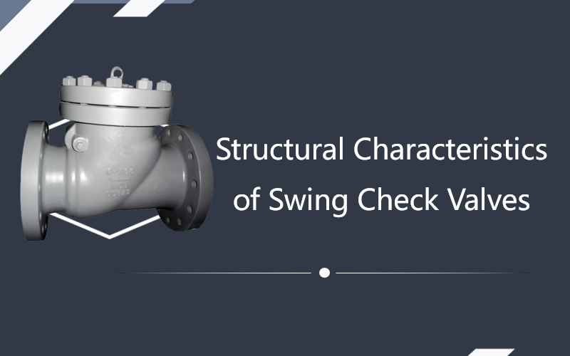
Structural Characteristics of Swing Check Valves
Dec 15, 2023
A swing check valve is a check valve in which the valve disc rotates around the rocker shaft in the body cavity. The opening and closing principle of a swing check valve is the same as that of a lift check valve, which also relies on the action of fluid pressure and the self weight of the valve disc to act on its own. The difference is that the opening and closing method of the valve disc is rotational motion rather than upward and downward movement, and the inlet direction of the fluid should be on the side that can impact the rotation of the valve disc. The closing component of a swing check valve is a valve disc or disc that is equivalent to the diameter of the pipeline, suspended inside the valve chamber. When the fluid flows forward, the valve disc opens under the action of fluid pressure, and when the pressure drops, the valve disc closes under the action of its own weight and the pressure of the countercurrent fluid. A swing check valve consists of a valve body, valve cover, valve disc, and rocker. The valve disc is in a circular shape and rotates around the pin axis outside the valve seat channel. The internal channel of the valve is streamlined, and the flow resistance is smaller than that of the straight through lifting check valve, making it suitable for large-diameter pipelines. But at low pressure, its sealing performance is not as good as the lift check valve. To improve sealing performance, auxiliary springs or heavy hammer structures can be used to assist sealing. Due to the weight of the valve disc, when a swing check valve opens, there is relatively greater resistance to the fluid. In addition, due to the valve disc being suspended in the fluid, it can cause turbulence in the fluid. This also indicates that the fluid pressure drop through swing check valves is greater than that through other forms of check valves. When the flow direction suddenly changes, the valve disc will fiercely close on the valve seat, causing significant wear on the valve seat and generating water hammer along the pipeline. To overcome this problem, a damping device can be installed on the valve disc and a metal seat can be used to reduce seat wear. According to the number of valve discs, swing check valves can be divided into three types: single disc, double disc, and multi disc. 1. Single disc type has only one seat channel and one disc, suitable for medium caliber swing check valves. 2. The double disc type has two valve discs and two seat channels, suitable for larger diameter swing check valves. 3. For large-diameter check valves, if a single disc structure is used, significant hydraulic impact will inevitably occur when the medium flows in the opposite direction, and even damage to the sealing surfaces of the valve disc and valve seat will be caused. Therefore, a multi disc structure is adopted. Its opening and closing components are composed of many small diameter valve discs. When the medium stops flowing or flows back, these small valve discs wil...
View More